This thread has been locked.

If you have a related question, please click the "Ask a related question" button in the top right corner. The newly created question will be automatically linked to this question.

TAS2557: the quickest way to use MCU to bring up TAS2557 with IIC command?

Part Number: TAS2557
Other Parts Discussed in Thread: PCM1808,

Hi,guys,

I want find the quickest way to use MCU to bring up TAS2557 with IIC command, how should I do?  I just want it can work and play music.

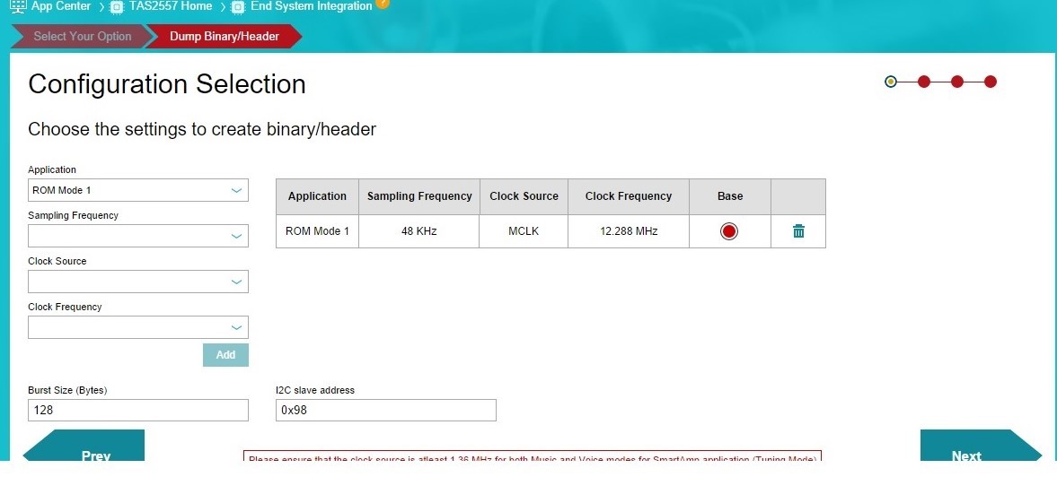
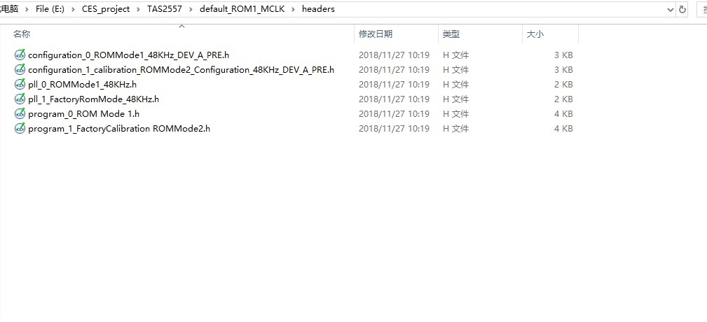
I use the PPC3 tool, all use the default settings without change anything, and dump the xx.h file as below:

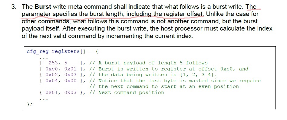
Should I write all the cfg_reg registers[] settings  in the xx.h file  to TAS2557 by IIC command?

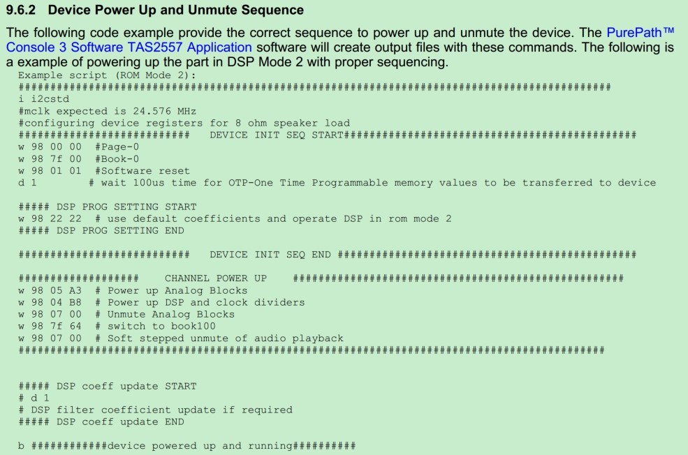
What is the relationsheep between the Device Power Up and Unmute Sequence and the xx.h file?

Thanks!

  • Hi,

    Welcome to e2e.
    In order to initialize TAS2557 through I2C commands, you should write the scripts obtained from the register dump in the following order:
    - Sotware_Reset (attached)
    - program_0**
    - pll_0**
    - configuration_0**
    - Unmute (attached)

    Best regards,
    -Ivan Salazar
    Applications Engineer - Low Power Audio & Actuators

    Scripts.zip

  • Hi, 

    I follow your guidance to write all IIC commands to TAS2557 as below:

    Sotware_Reset (as your attached)

    program_0_ROM Mode 1.h

    pll_0_ROMMode1_48KHz.h

    configuration_0_ROMMode1_48KHz_DEV_A_PRE.h

    Unmute (as your attached)

    But it still can't work, I make a 440Hz square wave input to the tas2557 by IIS with BCLK 3.072MHz, but there is no audio output.

    Does the ROM Mode 1 can output audio?

    In the end-System Integration, what is the MCLK  that I should use, (MCLK 12.288Mhz or  BCLK 3.072Mhz)?

    Thank you!

    my_headers.zip

  • Hi,

    I'll review your header files and give you some feedback tomorrow.
    ROM Mode 1 can playback audio.
    What is your I2S source? You should select MCLK or BCLK depending on your system.

    Best regards,
    -Ivan Salazar
    Applications Engineer - Low Power Audio & Actuators
  • Hi,

    thank you for reply.

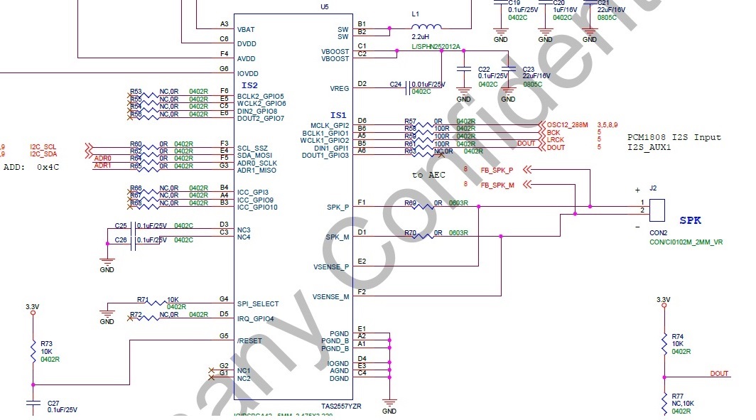
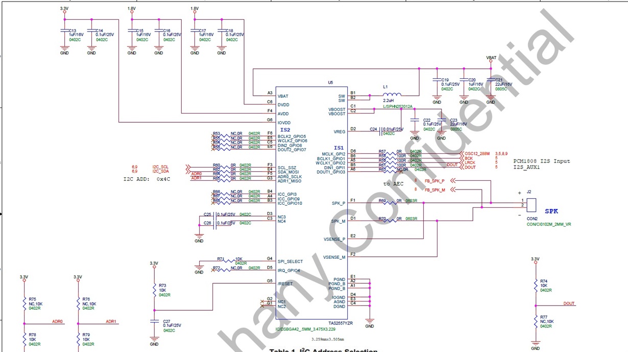
    Here is my tas2557 Schematic, 

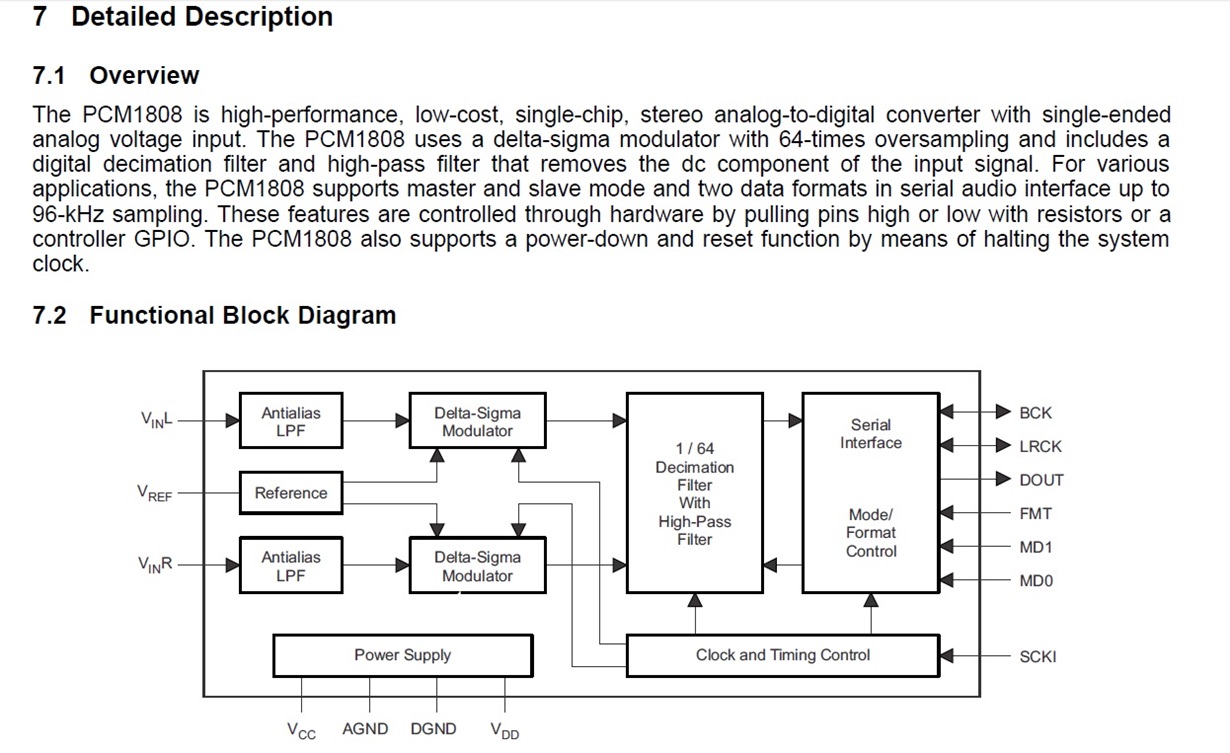
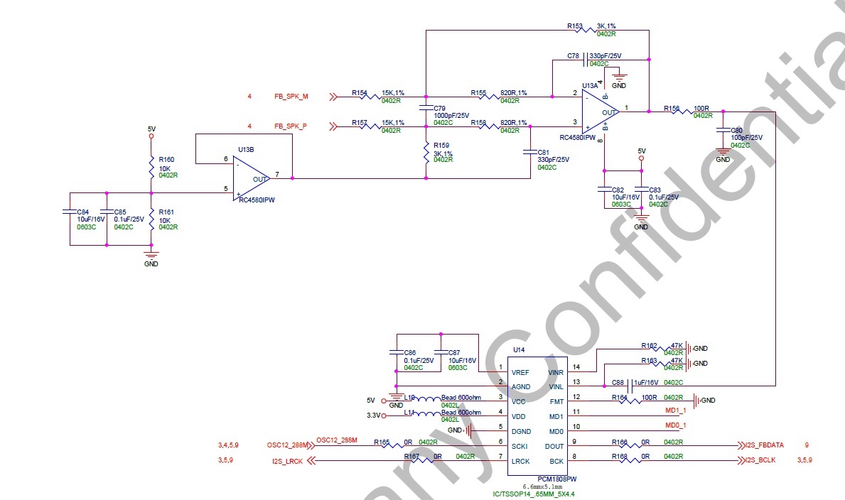
    The IIS source is an ADC (PCM1808) as the master, 

    and there is also a 12.288MHz OSC input as MCLK to tas2557.

    By the way, the Unmute scripts that you supply is a little different from the scripts that list in the Device Power Up and Unmute Sequence in datasheet.

    you supply:

    # Unmute
    d 02  #2ms delay
    w 98 00 00 #Page 0
    w 98 7f 00  #Book 0
    w 98 07 00 #Unmute analog blocks
    w 98 7f 64  #Switch to book 100
    w 98 07 00 #Soft stepped unmute of audio playback
    d 02   #2ms delay

    the datasheet:

    ################### CHANNEL POWER UP ####################################################
    w 98 05 A3 # Power up Analog Blocks
    w 98 04 B8 # Power up DSP and clock dividers
    w 98 07 00 # Unmute Analog Blocks
    w 98 7f 64 # switch to book100
    w 98 07 00 # Soft stepped unmute of audio playback
    ############################################################################################

  • Hi,

    Could you please share your headers in cfg format so I can try them on my side.

    Best regards,
    -Ivan Salazar
    Applications Engineer - Low Power Audio & Actuators
  • Sure,please see file attatched 

    one is using BCLK, and another is MCLK,

    please have a try.Thank you.

    default_ROM1_BCLK_3072.zipdefault_ROM1_MCLK_12288.zip

  • Hi,

    You should just use "combined_configuration..." file. Please just make sure to completely power up the device and provide digital input signals. The previous procedure is meant to be used for a stepped initialization.

    Best regards,
    -Ivan Salazar
    Applications Engineer - Low Power Audio & Actuators
  • Hi,

    I have just write all of the IIC cmds list in the file "combined_configuration_0_ROMMode1_48KHz.cfg",

    (I have seen that the cfg file is combined from the files,

    "pll_0_ROMMode1_48KHz.h"

    "program_0_ROM Mode 1.h"

    "configuration_0_ROMMode1_48KHz_DEV_A_PRE.h",

    and add some other cmds)

    but there is still no audio output.

    I have also confirmed that the tas2557 has power supply,

    I can readback the TAS2557's Device ID 0x12, 

    and I can readback other register values,  the value is just the same as what I write.

    There is also digital input signals into DIN1_GPI1,

    but there is no audio output on SPK_M and SPK_P.

    Does the "combined_configuration_0_ROMMode1_48KHz.cfg"  file can work normally in your side? 

    After supply power to tas2557, Does I just need to write all the cmds that list in "combined_configuration_0_ROMMode1_48KHz.cfg" file, and the tas2557 can output aduio?

    What about the "xxx.bin" file?  Do I need to use it?

    By the way, in my system, the tas2557 is slave, and the BCK(3.072MHz), LRCK(48KHz) comes from a ADC (PCM1808),

    In PPC3 tools, where is the place to config the tas2557 to be a master or to be a slave?  I just can't find it.

    combined_configuration_0_ROMMode1_48KHz.cfg

  • combined_configuration file worked on my side. Actually I used this file from the scripts you uploaded before.
    Yes, you should supply TAS2557EVM and then write combined_configurations file with I2C tool.
    TAS2557 is slave by default.

    Best regards,
    -Ivan Salazar
    Applications Engineer - Low Power Audio & Actuators
  • Hi, it is quite strange, I'm sure I have downloaded all the cmds list in the "combined_configuration_0_ROMMode1_48KHz.cfg",

    but there is still no audio output.

    Are there any registers that I can readback to detect whether the TAS2557 is working normally?

    By the way, this burst commands that I readback is a little different from what I actually write.

    In # Program  Part

    write:

    w 98 20 1d
    > 99  
    > 99
    > 99
    > 20
    > cc
    > cc
    > cc
    > 24
    > 00
    > 00
    > 00
    > 27
    > 33
    > 33
    > 33
    > 2a
    > 66
    > 66
    > 66
    > 2d
    > 99
    > 99
    > 99
    > 30
    > cc
    > cc
    > cc
    > 34
    > 00         change to   0xae    when I readback.
    > 00         change to   0x14    when I readback.
    > 00

    Is it normal?Auto changed?


    4251.combined_configuration_0_ROMMode1_48KHz.cfg

  • I get the same values as written when reading those registers:
    # Read command at line 4 : r 98 20 20
    1d 99 99 99 20 cc cc cc
    24 00 00 00 27 33 33 33
    2a 66 66 66 2d 99 99 99
    30 cc cc cc 34 00 00 00

    These registers contain DSP coefficients, I wonder why these are being modified on your test. These registers always change to the same values?

    Best regards,
    -Ivan Salazar
    Applications Engineer - Low Power Audio & Actuators
  • Yes, they always change to the same values.

    # Read command at line 4 : r 98 20 20
    1d 99 99 99 20 cc cc cc
    24 00 00 00 27 33 33 33
    2a 66 66 66 2d 99 99 99
    30 cc cc cc 34 ae 14 00

    and also the below cmds are also changed

    w 98 10 73
    > 33
    > 33
    > 33
    > 6b   changed to 6e when readback
    > 85   changed to 14 when readback
    > 1e   changed to 7a when readback
    > b8   changed to 00 when readback

    May they be changed by hardware auto config?

  • Are you using the EVM for these last tests?
    If not using the EVM, what are your clock frequencies? I'd like to compare this with the register settings. This might not be related to the change in the register values above, but I'd like to at least identify why there is no audio on your side.

    Best regards,
    -Ivan Salazar
    Applications Engineer - Low Power Audio & Actuators
  • Hi, 

    I don't use the EVM(acturally, I don't have a EVM),

    I'm using my own board.

    Below is my board's sch

    In PCM1808 part, there is only VINR has audio input(Tone, here is 440Hz square-wave), VINL is no audio input.

    Clock frequencies:

    BCK is 3.072MHz

    LRCK is 48KHz

    MCLK is 12.288MHz

  • Can you confirm that TAS2557 is not triggering any protection by reading Book 0 Page 0 Registers 0x64, 0x65 and 0x68?
    From the schematic, what are FB_SPK_P and FB_SPK_M connected to?
    On the other hand, have you verified PCM1808 operation with square-wave as input? Audio devices are not usually meant to be used with square-wave or PWM signals unless there is a filter.

    I have confirmed that cfg is working fine on the EVM with the same input signals: BCK is 3.072MHz / LRCK is 48KHz / MCLK is 12.288MHz
    Have you tried with a different I2S source than PCM1808?

    Best regards,
    -Ivan Salazar
    Applications Engineer - Low Power Audio & Actuators
  • Hi, 

    the FB_SPK_P and FB_SPK_M are connected to another PCM1808, and output to another Device for a feedback uses.

    and the PCM1808 has LPF and HPF, may it support square-wave as input?

    I have not test another IIS source now.

    the regs I readback is:

    Read Reg: 0x64, Data: 0xf0

    Read Reg: 0x65, Data: 0x00

    Read Reg: 0x68, Data: 0x02

    Read Reg: 0x6c, Data: 0x00

    (I have also try it on the EVM board, and the value is the same on the EVM borad)

     I'v get a EVM board now, and I have tryed to use the "combined_configuration_0_ROMMode1_48KHz.cfg" to init the TAS2557 EVM board by I2C Monitor,

    and it can work normally and output audio, so the cfg file is OK. 

    By the way,

    What is the "xxx.bin" used for? Is it used for the Android system,  and in my MCU system, I don't need to use it? Don't need to burn it to the TAS2557?

  • Hi, good news.

    I have finally fingured it out, 

    cause the "xxx.h" file genertate by the PPC3 tools has a problem,the length in CFG_META_BURST do not inclue the reg itself (it is different from what the Documnet introduced !!!)

    so the length should be +1 here,

    Now, I have connect my MCU to the TAS2557 EVM board, I can bring up the TAS2557 on the EVM board and make audio output normally, the audio source is from my computer. 

    On my own board, the TAS2557 can also be bring up, and can output PWM 440Hz square-wave audio normally too.

    Thank you very much!