This thread has been locked.

If you have a related question, please click the "Ask a related question" button in the top right corner. The newly created question will be automatically linked to this question.

INA137: Differential line receiver input protection

Part Number: INA137
Other Parts Discussed in Thread: INA317, INA1620, INA1650

Hello,

I'd like to use this INA137 differential line receiver in a system where someone may plug/unplug these inputs from an audio patch panel..so it will likely create transients. Can you please suggest an input protection schematic (with diodes and/or TVS) that will offer ESD and transient protection? The differential input signals will not be higher than +/-5V.

Thanks,

-Paul

  • Hi Paul,

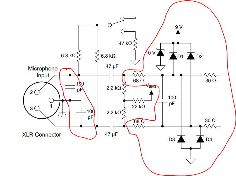
    Thanks for your question. I’d like to point you to an application circuit from our INA1620 datasheet (section 8.3.1). The ESD protection scheme used here can be reused in your application with the INA317:


    If an ESD event hits either input, it should be controlled somewhat by the 100pF capacitors, but any residual that couples across the 47µF blocking capacitors will get shunted to the supplies through D1-D4. Adding TVS diodes for the supplies is important here to ensure the ESD event is coupled back to ground. If the application isn’t single-supply, you may add a TVS diode to each supply and then tie D3 and D4 to the negative supply, rather than to ground.


    You may also look into the INA1650 as a modern differential line receiver with precision-matched on-chip resistors for high CMRR performance.

    -Tamara

  • Hi Tamara,

    Thanks for getting back to me. I have a few questions about this schematic..

    Is the 10V diode on the 9V supply a 10V zener diode or a 10V TVS? I was planning on adding another one to my negative 12V supply too.

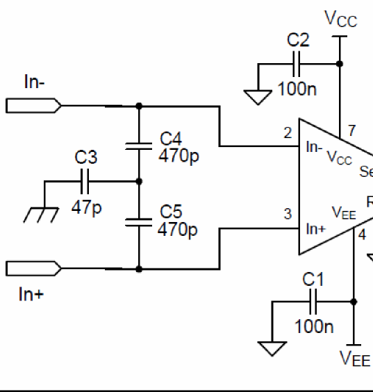
    About the input 100pF caps.. I was thinking about doing something very similar with the 100pF caps at the input, but I was also going to put another one between their common point and GND (see attached schematic).. do you see any issue(s) with this?

    I wasn't planning on using 68 Ohm and 30 Ohm resistors in my circuit.. so I might need to re-think that. This is for current limiting and decoupling op amp inputs?

    Thank you,

    -Paul

  • Hi Paul,

    the scheme with the diodes from Tamara is mainly meant to provide a protection against the phantom supply voltage. When the phantom power is activated by turning-on the switch, for a brief period the whole phantom supply voltage is injected into the signal path at the input of INA1620 until the both 47µF caps are charged up. And the both 100pF caps are not so much ESD protection but more EMI filtering against cellphone radiation. If these 100pF caps are really hit by ESD they should be rated for a voltage of 1kV or so.

    I would recommend to use actual ESD protection components instead of these both 100pF caps. TI has bipolar TVS with <100pF junction capacitance and little leakage currents for this purpose. Keep in mind, that the TVS must also be able to withstand the phantom supply voltage, if you apply some. Or you could use a low leakage SMD varistor with <100pF parasitic capacitance. I think AVX has nice parts.

    Also, ESD should be shunted to the chassis, if you have some. Don't ever allow ESD to enter your circuit! ESD can be shunted to the chassis by using hybrid bonding directly at the microphone connector. Mount a 10nF cap from signal ground to chassis ground directly at pin 1. And mount the ESD components directly from pin 2 and pin 3 to pin 1. Of course, if your application allows, you can directly connect pin 1 to chassis ground.

    You can enhance the EMI filtering by using a PI filter scheme, with the ESD component at the input and a 470...1000pF NP0 ceramic cap at the output of PI filter. Connect the ESD component and the ceramic cap with a ferrite bead to form a PI filter. Do this for both microphone lines. This whole scheme should sit very close to the microphone connector.

    The 68R and 30R resistors are quite useful. They limit the currents into the protection diodes' scheme and into the OPAmp. They also minimize resonances. So, they absolutely make sense. The 10V zener should have a 100nF in parallel to absorb the fast residual ESD currents. Then, it plays no role whether a standard zener or a special ESD capable TVS is used at this place.

    Unfortunately, the ferrite bead is no good barrier for ESD currents, because they easily drive the ferrite material into saturation causing the ferrite bead's impedance to heavily decresase. So, in any case the diodes' protection scheme is still necessary. I would take the BAV99 as protection diode.

    Kai

  • Hello Kai,

    Thanks for your response, and great explanations!

    My system actually doesn't use phantom power.. it has +/-12V power rails, and the audio signals are +/-5V (balanced) differential input, and +/-10V single-ended output. So no XLR/mic connector.. just several1/8-inch jacks.

    And I wasn't planning on using any series capacitors though on the signal line. In the above application example circuit from Tamara, are those for caps for AC coupling or low-pass filtering? Or some requirement for phantom power?

    So I'll use series resistors then..for the reasons you mentioned. And probably just zener diodes with 100pF caps in parallel (instead of TVSs..depending on pricing).

    Also in your 4th paragraph where you describe a Pi-filter scheme for EMI.. just to make sure I'm visualising this correctly.. this is just 2 caps separated by a series ferrite bead? One side goes to the input, the other to the op-amp's input, correct?

    I was going to use 4004 diodes (which is a little overkill for my appication), so thanks for suggesting BAV99!

    -Paul
  • Hi Paul,

    I would do it this way:

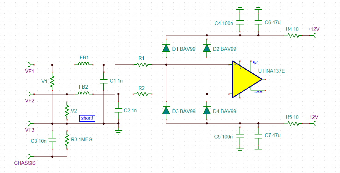
    V1 and V2 stands for the SMD varistors or TVS to clamp ESD to signal ground. Then the ESD currents are shunted from signal ground to chassis via hybrid bonding. The ESD protection parts can have a parasitic capacitance of up to 100pF or so. Choose parts with low leakage currents, though, which can easily withstand the maximum input signal voltage.

    V1 and V2, the ferrite beads FB1 and FB2 and the NP0 ceramic caps C1 and C2 form PI filters. I wouldn't increase the capacitances C1 and C2 to over 1nF, because these capacitances also present a capacitive load to the output stage which drives the INA137 input. That said, in some mixing consoles capacitances of up to 2.2nF can be seen.  Also, FB1 and FB2 need not necessarily to be ferrite beads but can also be standard chokes. Chokes of up to 330µH can be seen in some mixing consoles. But I think to filter cellphone frequencies the ferrite bead is the much better choice. It also improves the suppression of ESD.

    R1 and R2 are a bit critical. For protection purpose they should be high. But high resistor values can degrade the symmetry of input circuitry of INA137 and by this ruin the common mode rejection. See the section "applications information" of datasheet of INA137. So, I would use something between 4R7 and 47R. Take 0.1% resistors, if you can. In any case you should check by measurement whether they have any unwanted impact on the common mode rejection of INA137.

    Keeping R1 and R2 small is not so much of a disadvantage as it seems at the first sight, because the BAV99 can withstand huge currents, if the current flow lasts very shortly, which is the case for ESD currents. Also, the residual ESD currents through the BAV99 are heavily reduced by the action of the ESD absorbers V1 and V2 and the PI filters. So, the BAV99 only have to withstand rather little residual ESD currents.

    Another issue is, when the INA137 is powered down while being driven by an input signal. In this case the BAV99 will profit from the output current limitation of the driving output stage. But even if the driving output stage isn't current limited, 5V / 47R is only 106mA, which the BAV99 can easily withstand.

    In the supply voltage lines of INA137 you can see RC low pass filters. When it comes to audio I often use such RC low pass filters. The 47µF cap is a standard aluminium electrolytic. The advantage of this "huge" decoupling cap is, that the residual ESD currents flowing through the BAV99 can be fully absorbed by this capacitance. So, a zener diode clamp across the supply voltage pins of INA137 might no longer be needed.

    Kai