This thread has been locked.

If you have a related question, please click the "Ask a related question" button in the top right corner. The newly created question will be automatically linked to this question.

Compiler/TLV320AIC3104: Single-ended input acquisition data transmission DSP

Part Number: TLV320AIC3104

Tool/software: TI C/C++ Compiler

Hi TI

We want to input two sets of different signals through a single terminal to collect and transmit the collected data to the dsp. One of them is not used and can be turned off.

Here is the code for validation:

config  init code

aic3104_register_write(101, 0x00); ///  CODEC_CLKIN uses PLLDIV_OUT

aic3104_register_write(3, 0x93); //// PLL enable, PLL Q value: 2 ,PLL P value: 3

aic3104_register_write(4, (0x04<<2) & 0xfc); //// PLL J value: 4

aic3104_register_write(5, ((0 << 2)>>8) & 0xff); /// PLL D value: (0  *4) /  256

aic3104_register_write(6, (0 << 2) & 0xff); //// PLL D value: (0  *4) %  256

aic3104_register_write(11, 0x04); //// PLL R value: 4


aic3104_register_write(8,0xD0);

aic3104_register_write(9,0x47); //// DSP mode


aic3104_register_write(2, 0xAA); //// ADC and DAC fs, delate this for 48K, use this for 8K


aic3104_register_write(17, 0xFF);

aic3104_register_write(18, 0xFF);

aic3104_register_write(19, 0x78);

aic3104_register_write(21, 0x78);

aic3104_register_write(22, 0x78);

aic3104_register_write(24, 0x78);


aic3104_register_write(26, 0x00);

aic3104_register_write(28, 0x00);

aic3104_register_write(29, 0x00);

aic3104_register_write(31, 0x00);


aic3104_register_write(32, 0x00);

aic3104_register_write(33, 0x00);


aic3104_register_write(15, 0x00);

aic3104_register_write(16, 0x00);


// aic3104_register_write(25, 0x80);   

aic3104_register_write(7, 0x0C);

aic3104_register_write(37, 0xC0);

aic3104_register_write(43, 0x00);

aic3104_register_write(44, 0x00);

aic3104_register_write(82, 0x80); ////  DAC_L1 is routed to LEFT_LOP/M.

aic3104_register_write(86, 0x8B);

1. 

Open mic2R to left adc

aic3104_register_write(7, 0x00);

aic3104_register_write(37, 0x00);

aic3104_register_write(82, 0x00);

aic3104_register_write(86, 0x02);

aic3104_register_write(17, 0xF0);

aic3104_register_write(19, 0x7C);

In this way, the test DSP can receive data.

2. 

Open mic1RP to right adc configured in single-ended mode


aic3104_register_write(7, 0x00);

aic3104_register_write(37, 0x00); 

aic3104_register_write(82, 0x00);

aic3104_register_write(86, 0x02);

aic3104_register_write(22, 0x04);

In this way, the test DSP did not receive data.

Why? Do you have any suggestions?

Thanks.

Jerry

  • Hello Jerry,

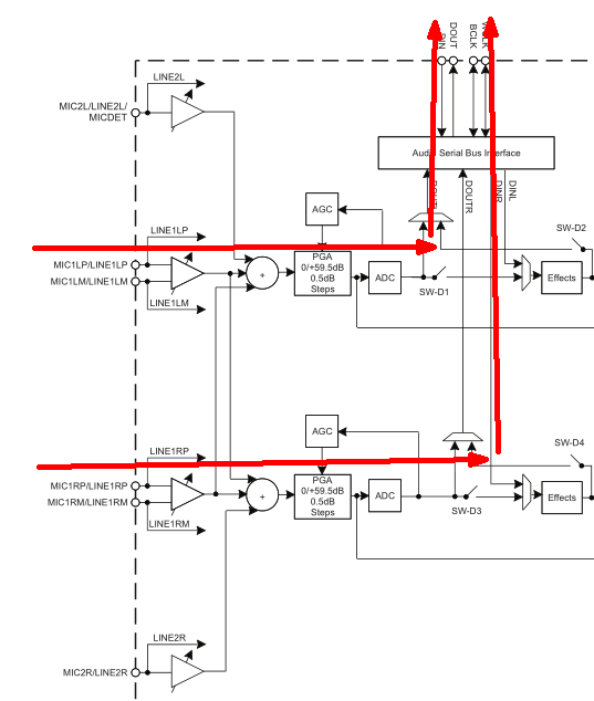
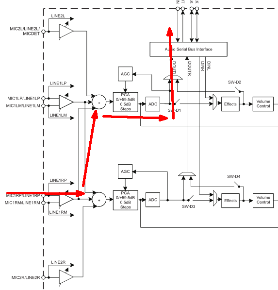
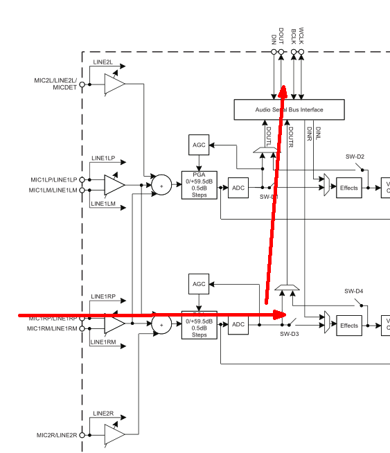
    You said you are applying two different differential signals on the same terminal.... what terminal are you using? My apologies but the pictures you are providing are a little misleading to me. 

    Also are you trying to configure the TLV320AIC3104 in master mode?

    Regards,

    Aaron

  • hello Aaron,

    this is our demand.5483.3104MIC2.doc

    we are applying two  different differential input signals on the same terminal . a input single input terminal to collect and transmit the collected data to the dsp. One of them is not used and can be turned off. or two  different differential input signals input terminal to collect and transmit the collected data to the dsp. 

    we are applying two  different differential input signals on the same terminal ,the  input signal to MIC2L->L PGA ->L ADC -> DOUTL and the other input signal to MIC2R->R PGA ->R ADC -> DOUTR. but the test DSP can nots receive DOUTR data.

    We want to input signals through a single terminal to collect and transmit the collected data to the dsp. One of them is not used and can be turned off.

    the  input signal to MIC2L->L PGA ->L ADC -> DOUTL. RADC power down. In this way, the test DSP can receive data.

    the  input signal to MIC2R->R PGA ->R ADC -> DOUTR. LADC power down. In this way, the test DSP can't receive data.

    Why? Do you have any suggestions?

  • Hello,

    The above images from the post and the images in the Word document do not match up. If you are applying differential inputs to MIC2L/MIC2R, you cannot. MIC2L/MIC2R are single-ended inputs and cannot be configured as differential inputs. 

    Regards,

    Aaron

  • hello Aaron,

    I am sorry, Error may be described.4150.3104MIC2.doc

    we are applying two  different single-ended input signals on the same terminal . 

    a input single input terminal to collect and transmit the collected data to the dsp. One of them is not used and can be turned off. or two  different single-ended input signals input terminal to collect and transmit the collected data to the dsp. 

    We want to input signals through a single terminal to collect and transmit the collected data to the dsp. One of them is not used and can be turned off.

    we are applying two  different single-ended input signals on the same terminal ,

    the  input signal to MIC2L->L PGA ->L ADC -> DOUTL and the other input signal to MIC2R->R PGA ->R ADC -> DOUTR. but the test DSP can not receive DOUTR data.

    LADC power up. RADC power up.In this way,  Can you describe how DOUT data output?


    the  input signal to MIC2L->L PGA ->L ADC -> DOUTL. RADC power down. In this way, the test DSP can receive data.

    LADC power up. RADC power down.In this way,  Can you describe how DOUT data output?


    the  input signal to MIC2R->R PGA ->R ADC -> DOUTR. LADC power down. In this way, the test DSP can't receive data.

    LADC power down. RADC power up.In this way,  Can you describe how DOUT data output?


    Why? Do you have any suggestions?

  • User, 

    I think you need to clarify your setup. 

    You have said you are applying signal on MIC2L/R and MIC1R,  that is three inputs.  Two of which are only available as single ended inputs. 

    Your diagrams also don't match your descriptions and it shows the inputs on mic1L and Mic1R

    We are not able to help if the problem statement is not consistent.  

    Please restate your problem,  with the exact input pins you are using.  If you are hooking up a differential signal,  then explain which pins you connect the Singal-P and Signal-M  (plus and minus)

    best regards,

    -STeve Wilson

  • dear  STeve:

    I am applying signal on MIC2L/R , not MIC1R. the MIC2L and MIC2R are  single ended inputs.

    my diagrams  match my descriptions and it shows the inputs on mic2L and Mic2R, show the follow document.

    Please give priority to with the document, don't pay attention to the original hair problems.

    6470.3104MIC2.doc

  • User, 

    I have tested your configurations on our EVM and reported back to you in another thread. The result on the EVM is that the AIC3104 performs as expected. I get data with both configurations. 

    I assume that you have resolved this issue? 

    best regards,

    -STeve Wilson