This thread has been locked.

If you have a related question, please click the "Ask a related question" button in the top right corner. The newly created question will be automatically linked to this question.

TAS2505-Q1: 25k sampling rate without MCLK question

Part Number: TAS2505-Q1
Other Parts Discussed in Thread: , TAS2505

Hi TI,

Due to MCU limitation, we do not have general audio sampling rate, such as 8k, 16k, 48kHz. Currently, we have 10k, 25k and 50kHz options. Below is the application circuit:

  • TAS2505-Q1 is I2S slave without MCLK input
  • Use BCLK as PLL clock input
  • Only 5V as SPKVDD, 3V3 as IOVDD
  • LDO_SEL is high, connect AVDD and DVDD together, using internal LDO
  • I2S: BCLK=800kHz, WS=25kHz, 16bit depth


I have tested another media source with the same configuration but 48kHz sampling, it works. Then, I modified the clock setting to fit TAS2501-Q1 requirement. My setting is as below:

  • BCLK is 800kHz and as PLL_CLKIN
  • P=1, R=4, J=28, P=1
  • PLL_CLK is 89.6MHz and as CODEC_CLKIN
  • NDAC=2, DAC_CLK is 44.8MHz
  • MDAC=7, DAC_MOD_CLK is 6.4MHz
  • DOSR=256, DAC_fs is 25kHz
  •  

For more detail, please refer to attached config file.PGWW20_ClassD_playback_FS25k.cfg

However, I hear the high frequency tone, not 1kHz tone. What I would like to confirm are

  1. Can TAS2505-Q1 input support 25kHz sampling?
  2. Is my setting correct?
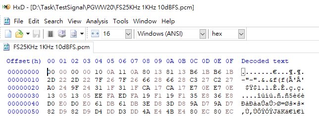
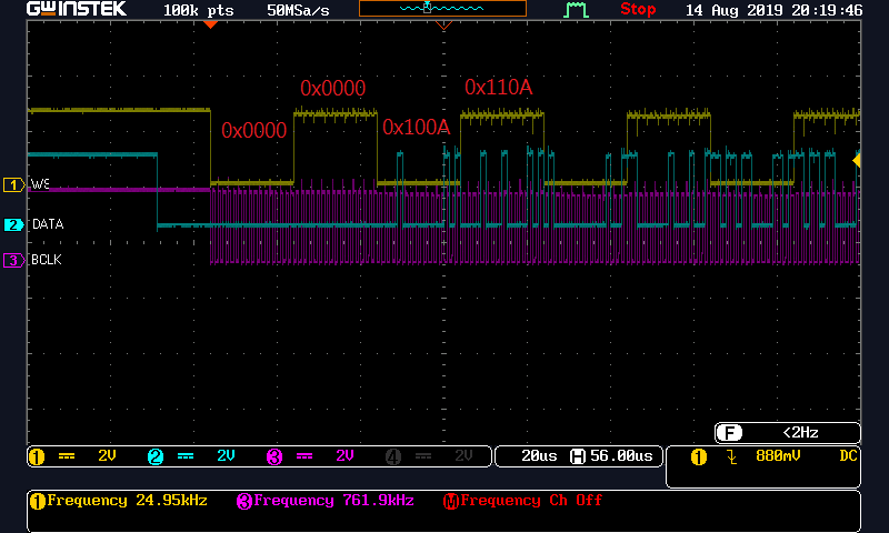
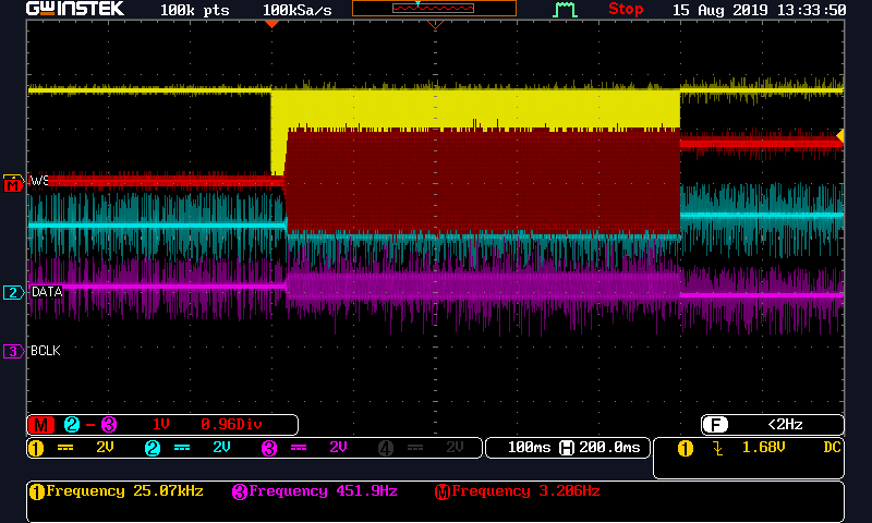
  3. Since the I2S driver is software control, I am worried about the data format: below is the pcm raw data and actual waveform:

  • I would like to attach the pcm raw data, but it seems not work. If you are interesting in, please let me know. I could send it by email.

    - fs=25kHz

    - 16bit

    - stereo

    - 1kHz tone, -10dBFS, 0.5s

  • Hi, Nick,

    You shouldn't have issues with your configuration. I tested it with the help of our TAS2505-Q1EVM and it works correctly. I can get a correct sine wave. I also tested a different configuration with our suggested PLL values and it works fine too.

    TAS_SPK_Playback_25KHz.txt
    # Playback Class-D
    # Page switch to Page 0
    W 30 00 00
    # Assert Software reset
    W 30 01 01
    # Page Switch to Page 1 
    W 30 00 01
    # LDO output programmed as 1.8V and Level shifters powered up.
    W 30 02 00
    # Page switch to Page 0
    W 30 00 00
    # Dac Instruction programming PRB #1 
    W 30 3c 01
    # CODEC_CLKIN=BCLK.BCLK should be 800KHz
    W 30 04 07
    # PLL values: P=1, R=4, J=28, D=0
    w 30 05 94 1C 00 00
    # Codec Interface control Word length = 16bits.BCLK&WCLK inputs.I2S mode.
    W 30 1b 00
    # Data slot offset 00
    W 30 1c 00
    # DAC NDAC Powered up, NDAC=4
    W 30 0b 84
    # DAC MDAC Powered up, MDAC=7
    W 30 0c 87
    # DAC OSR(9:0)-> DOSR=128
    W 30 0d 00
    # DAC OSR(9:0)-> DOSR=128
    W 30 0e 80
    # Only LDAC powered up.Dac path setup LDAC data Mono of LDAC and RDAC. RDAC data disabled.Soft step 1 per Fs.
    W 30 3f B0
    # DAC volume for Left channel not muted.Right DAC muted.
    W 30 40 04
    # LDAC digital gain 0dB
    W 30 41 00
    # Page Switch to Page 1
    W 30 00 01
    # Master Reference Powered on
    W 30 01 10
    # Output common mode for DAC set to 0.9V (default)
    W 30 0a 00
    # LDAC AFIR is 6th order FIR filter and Powered up.
    W 30 03 00
    # SPKL attn. Gain =0dB
    W 30 2E 00 
    # SPKL driver PGA Gain=6.0dB 
    W 30 30 10
    # SPK OSCP enabled , OCP Degltich=4, OTP enabled , OTP Deglitch=5
    W 30 52 00
    # SPK powered up
    W 30 2D 02


    Is your data in 2's complement signed PCM format?

    Do you have an Audio Precision tool to test the sine wave data from an I2S transmitter?

    Best regards,
    Luis Fernando Rodríguez S.

  • Hi Luis,

    I noticed that the PCM raw data format is LSB,MSB. We transferred to MSB,LSB, then it works, both output voltage and frequency are correct. But I found below issue that at the end of I2S, we will stop the BCLK along with data, it seems the digital processing of TAS2505 stop at the meanwhile, so the waveform stop at a certain voltage. (yellow is WS, and red is AMP output with LC filter)

    I tried add 0 data to keep BCLK for extra 1ms, the issue is gone. So my question are, is it reasonable that DAC stops when BCLK stops? if yes, how much the duration I have to keep BCLK working?

    I looked your setting, some questions about it

    (1)  Page 1, register 2, D2: Reserved. Don't write any value other than Reset Value.(reset=1)
    # Page Switch to Page 1
    W 30 00 01
    # LDO output programmed as 1.8V and Level shifters powered up.
    W 30 02 00

    (2) Page 0, register 63, D2-D3 is reserved, Write only default values. (default=01)
    # Only LDAC powered up.Dac path setup LDAC data Mono of LDAC and RDAC. RDAC data disabled.Soft step 1 per Fs.
    W 30 3f B0

    Are the above two questions typo or there are new definition?

  • Hi, Nick,

    The BCLK and the DAC processing blocks are always associated for the beginning and the end of the internal activity. Generally, the processing blocks require of at least 8 BCLK pulses in order to start its digital processing. Similarly, these blocks require of around 8 BCLK pulses to finish its activity.

    Regarding the settings that I shared, these are the settings that we use as initialization code for our TAS2505-Q1EVM. You may use your current settings if these code lines don't apply to your configuration.

    Best regards,
    Luis Fernando Rodríguez S.

  • Hi Luis,

    Got it. You really help me a lot.

    Regards,

    Nick.