This thread has been locked.

If you have a related question, please click the "Ask a related question" button in the top right corner. The newly created question will be automatically linked to this question.

TLV320DAC3101: TLV320DAC3101IRHBR

Part Number: TLV320DAC3101

1. Project Background:TLV320DAC3101IRHBR is used for the project of DOCKING connectd to mobile phone by TYPEC3.1 cable.   I2S audio of TLV320DAC3101IRHBR is separated from  DISPLAY singal. Speaker is 2-W,  4-Ω speaker.  Register parameter is writed in chip by I2C of other chip for no driver.

2. Issue A:When I Adjust the volune from 100% to 0,  the horn sound become very small about 50%.  Result of a measurement sperker is as follow,   when phone play 1Khz voice.

          100% : peak-to-peak value of speaker  is  6.2V.                       50% : peak-to-peak value of speaker  is  1V

    Issue B :  playing some song,    I can hear  cracking voice.

           TLV320DAC3101IRHBR.docx

  • Hi!

    Excuse me, are you using a 4ohms speaker connected to the TLV320DAC3101? The TLV320DAC3101 supports loads down to 8 ohms. This may result in a wrong device operation and there's a high risk to damage the device.

    Best regards,
    Luis Fernando Rodríguez S.

  • Hello,

             Yes, I use 4ohms speaker connected to the TLV320DAC3101.  

    Measurement result of a  8 ohm sperker is as follow,   when phone play 1Khz voice.  

    100% : Max peak-to-peak value of speaker  is  5.8V.           50% : Max peak-to-peak value of speaker  is  1.01V

    Measurement result of no sperker is as follow,   when phone play 1Khz voice. 

    100% : Max peak-to-peak value of speaker  is  6.6V.           50% : Max peak-to-peak value of speaker  is  1.17V

    So the issue is not related to 8ohm or 4ohm speakers.  What do you give suggestions for me as well?  In addition, can you provide register parameter list of woring properly ?

  • Hi,

    I reviewed the registers configuration and everything seems to be in order. I have only few questions about it.

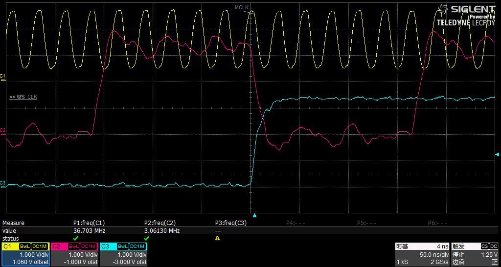
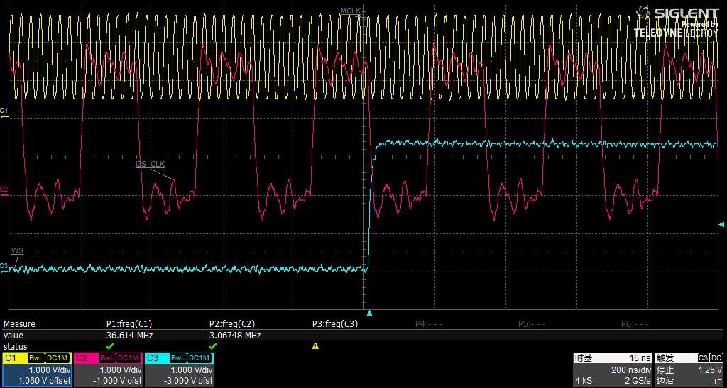
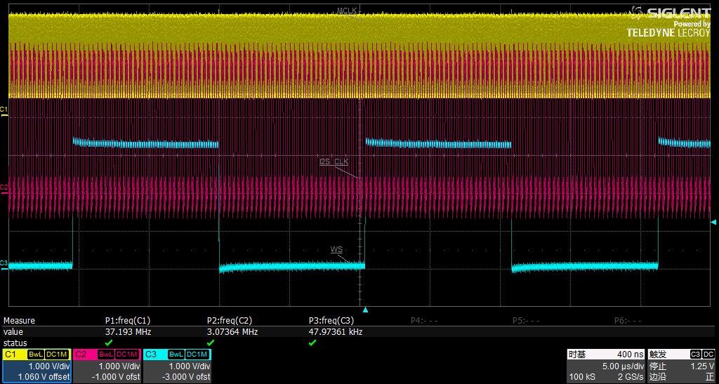
    - Could you provide the I2S clocks that you are using? Just to confirm that the PLL values are correct.
    - Could you explain how do you configure the volume registers to obtain the 100% and the 50% of volume level? It is not clear in the registers settings that you provided.

    I also checked the schematic and everything is correct. I have no observations on this.

    Thank you.

    Best regards,
    Luis Fernando Rodríguez S.

  • - Could you explain how do you configure the volume registers to obtain the 100% and the 50% of volume level?-----we only write register parameter for the initialization of the chip when main board power on, and then there are not data writed in chip by I2C expect headphone plugging.  the I2S clocks are as follow: 

  • Hi,

    The maximum volume level depends of the volume level block that you are using. Let me explain it below.

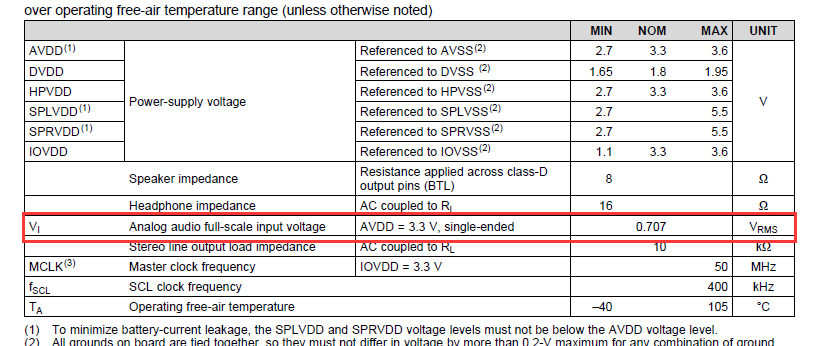
    For the digital volume block, the maximum voltage that it can allow is the full-scale voltage, which is 0.707Vrms as explained in page 7 of the datasheet. If the voltage level is increased, your signal will be clipping. So, it is important to not exceed this level in the digital volume block.

    However, your speaker driver may be configured to reach up to 1.29W at THD+N = 10% for a 8ohms load in BTL configuration. We could say that your 100% volume is the gain that reaches this value (in case you require of this THD+N level).

    In case of the headphone driver, we could say that the maximum volume/gain level is the one that reaches 60mW for a 16ohms load or 20mW for a 32ohms load.

    I hope this is clear. Please let me know if you have additional questions or comments.

    Best regards,
    Luis Fernando Rodríguez S.

  • Hi,

         For the digital volume block, the maximum voltage that it can allow is the full-scale voltage, which is 0.707Vrms as explained in page 7 of the datasheet. If the voltage level is increased, your signal will be clipping. So, it is important to not exceed this level in the digital volume block.

    ------------I want to know how to measure or where to measure the full-scale voltage ,and then judge whether it more than 0.0707Vrms or not.  

  • Hi,

    You may try sending a 1-KHz digital sine wave signal at full-scale level. Remember that the data range is in 2's complement signed format. So, the data will go from 0x8000 to 0x7FFF (in 16-bits format). If you send a digital sine wave with your audio serial interface and configure all the volume blocks with a 0dB gain, you should see a 0.707Vrms signal at the headphone output. The Class-D output can be only configured with a minimum 6dB gain, so this should be taken in account when the full-scale signal is sent to this output.

    Let me know if you have questions or comments on this.

    Best regards,
    Luis Fernando Rodríguez S.