This thread has been locked.

If you have a related question, please click the "Ask a related question" button in the top right corner. The newly created question will be automatically linked to this question.

TLV320ADC3140: Question for TLV320ADC3140 GPIO input to support I2S data input

Part Number: TLV320ADC3140

Hi Experts,

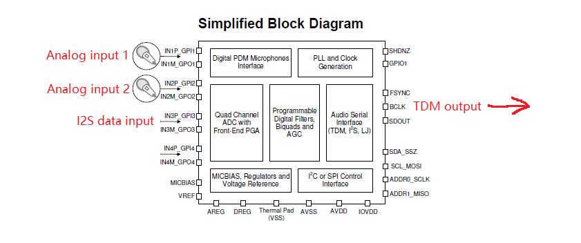
Our customer wants know if our TLV320ADC3140 GPIO pins can support I2S data input function like ES7243, can you help to check if we can do this or not?

ES7243 TDMIN function(customer used as the I2S data input, then combined another two channels analog input to TDM output):

http://www.csjwell.com/home/3/3/anlr9q/resource/2017/08/14/5991c65bbf580.pdf

Can we achieve below function using TLV320ADC3140?

Thanks.

  • Jacky, 

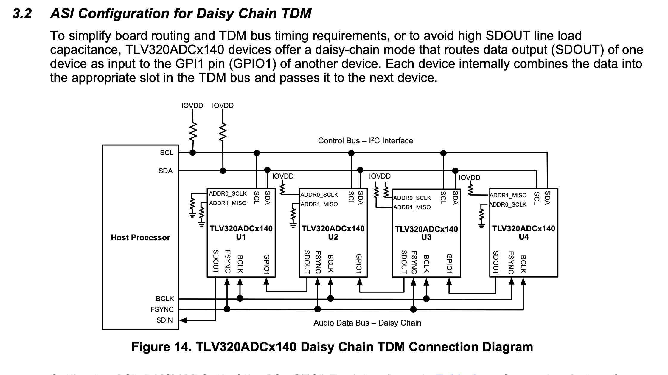
    If the I2S data can support the Same TDM clocks,  then yes this is possible.  This would be considered Daisy chain

    best regards,

    -Steve Wilson

  • Hi Steve,

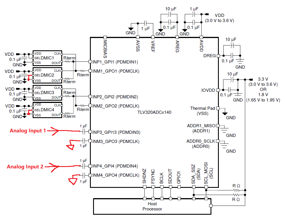
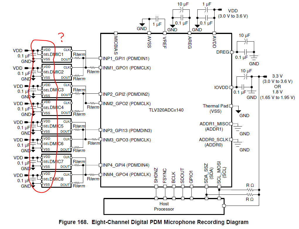
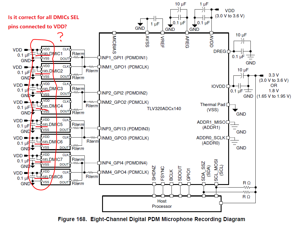
    Thanks for your kind reply. There should be some misunderstanding previously for customer. Now we determined the design is like below - two analog signals input from their speaker by dividers, and 4 DMICs. We know that it could be supported by our device. But we see that in our datasheet  reference block diagram for 8 DMICs application, all DMICs SEL pin is connected to VDD, is it correct? As our understanding, it should be one is connected to VDD, and another is GND. Please help to check.

    Customer's application is fixed as below:

    Is it correct for all DMICs SEL pin connected to VDD in our datasheet?

    Thanks.

  • Jacky,

    The ADCx140 can support the following DMIC+analog input configurations:

    0DMICS + 4 analog inputs

    2DMICs +3 analog inputs

    4DMICs +2 analog inputs

    6DMICs + 1 analog input

    8DMICs +0 analog inputs

    If I am understanding correctly,  you want to use 4 dmics and 2 analog inputs.  This is definitely supported. 

    best regards,

    -Steve wilson

  • Hi Steve,

    Thanks for the reply. We understand that our device can support 2 channels analog input plus 4 DMICs, but we want to check why all DMICs SEL pin should be pulled high in our datasheet reference application as below - is it correct?

  • Hi Steve,

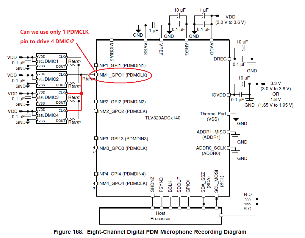
    Here comes another question: as customer's 4 DMICs were build as a module with only 3 signals(PDMCLK, PDMDOUT1, PDMDOUT2), where all DMICs CLK share one PDMCLK signal. So we want to check with you - can we use only 1 PDMCLK pin for TLV320ADC3140 to drive 4 DMICs?

    Thanks.

  • Jacky, 

    The SEL pin on the digital mics definitely should alternate between high and low for each pair of PDMINs. DMIC4 needs a PDMCLK also. 

    Regarding the PDMCLK, I don't see an issue here, but I will double check with our Design team to confirm there are not timing issues.

    best regards,

    -Steve Wilson

  • Jacky, 

    It is perfectly fine to use a single PDMCLK for all PDM microphones. Note that board routing and the mics they are using will increase load capacitance on the PDMCLK and that would increase the rise/fall time of PDM clock.  I would imagine that they understand that,  and if they do and don't mind, then it should be ok.

    best regards,

    -Steve Wilson

  • Hi Steve,

    Thanks for the confirmation. BTW: can you kindly help to give us some example configurations for such DMICs input plus two channels analog differential input?

    I only see either all analog input examples or all DMICs input examples in the datasheet.

    Thanks a lot!

  • Hi Steve,

    We are trying to configure our device based on customer's use case on our EVM, but it looks like not work as we expected. Attached is my PPC3 project file we configured, can you kindly help to take a look at it what's the problem in here?

    4 DMICs+2 Diff Analog Input_3-3-2020.ppc3

    We put the DMICs on GPI1 and GPI2, and two channel analog input on IN3 and IN4. After the configure, we will not see DMIC data on GPI2(GPI1 works fine), also analog input IN3/IN4 data will located in Slot 2/3 rather than Slot 4/5. What's the problem in here?

  • Jacky,

    You were really close to having it right,  the main issue was that you had GPI2DMICs set to PDM input channels 3 and 4,  but you can't do that if you are using analog channels 3/4.  I've attached an updated ppc3 file where I've assigned GPI2 to PDM channels 5/6 and reordered the Slots for you. 4 DMICs+2 Diff Analog Input_Updated.ppc3

    regarding the output slots

    GPI1 PDM MICS are on Slots 0-1

    GPI2PDM mICS are on Slots 2-3

    Analog inputs (ADC3/4) are on slots 4-5

    best regards,

    -Steve Wilson

  • Hi Steve,

    Thanks for the reply. We tried to test the ppc3 file you updated, but it looks like there is still having issues. We try to disconnect all DMICs from our EVM, but you will still see data output from the ADC. Can you help to verify for this?

    Also, regarding to below setting, can you help to give more detailed explanation? I'm not fully understand about this pin mapping.

  • Jacky, 

    regarding your data on the output without any digital mics,  I wouldn't expect data that looked like that.  With the absence of a PDM input,  the signal should essentially be saturated.   so there should be something there,  but what you're seeing looks like a lot of signal.  Can you give some more information here?

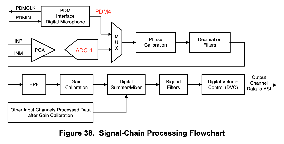
    regarding your settings for GPI2,  There are 8 digital channels in the device,  the inputs to channels 1, 2,3 and 4 can either be the ADC OR a PDM input.  So for channel 3,  you can use ADC3 OR PDM3, and for channel 4 the input can be ADC4 or PDM4

    I've modified the signal chain block diagram from the datasheet to demonstrate:

    Because you are using ADC3 and ADC4,  you cannot assign the PDM mics received on GPI2 to "PDM input CH3/Ch4"  The PDM inputs can be instead routed to channels 5 and 6.  I then grouped the PDM mics together in the flexible Audio Serial Interface.  So ch5 and ch6 use output slots 2 and 3.  which places them next to PDMchannels 1 and 2 which use output slots 0 and 1. 

    Best regards,

    -Steve Wilson

  • Hi Steve,

    "regarding your data on the output without any digital mics,  I wouldn't expect data that looked like that.  With the absence of a PDM input,  the signal should essentially be saturated.   so there should be something there,  but what you're seeing looks like a lot of signal.  Can you give some more information here?"

    Yes, I'm also confused about this. Please refer to below my setup - I just simply leaving DMICs input floating and run the PPC3 file like below. Can you also check it on our EVM in your side? It should be easily verified on our EVM.


    Thanks.

  • Hi Steve,

    Any feedback for the DMICs data issue?

    Thanks a lot!

  • Jacky, 

    I would not expect this behavior, I have reproduced it on my end, and wait for feedback from the design team.  oddly I see the noise on some digital channels while seeing negatively saturated output on others.  

    I will let you know what the design team says. 

    best regards,

    -Steve Wilson