This thread has been locked.

If you have a related question, please click the "Ask a related question" button in the top right corner. The newly created question will be automatically linked to this question.

LM48511: Noise when enabled, while no audio input is present

Part Number: LM48511

My issue seems to resemble the previous post "LM48511: Noise when amp enabled, while no audio input is present." 

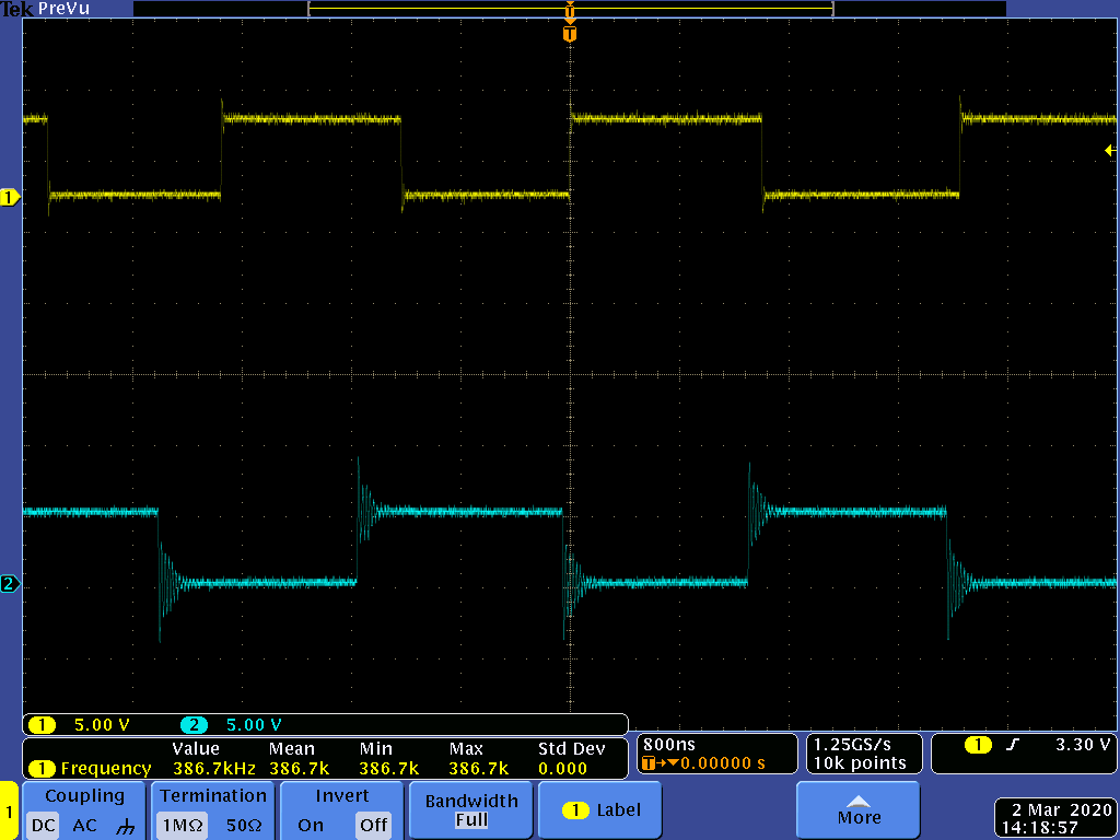
I have tested the board with boost on and off and with the boost off it is improved slightly.  It does seem like the issue is with the H bridge switching.  There seems to be some ringing on the output of the PWM and I am wondering if that is the issue.  I have not tried to put any sort of filtering on the output.  Was there any resolution to the issue posted in the forum previously?  The layout could be the issue; I have ordered the evaluation board to see if the output is cleaner than our implementation version.  

I can provide graphs and data, but the data looks very similar to the data posted already in the forum.

  • Hi, Andrew,

    Welcome to E2E and thank you for your interest in our products!

    Could you provide your circuit schematic and the layout is possible? Also, if you could also share details about the output measurement and how you are taking the captures/measurements, it will be also helpful.

    Thank you.

    Best regards,
    Luis Fernando Rodríguez S.

  • Ok here is some more information:

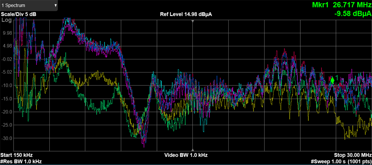
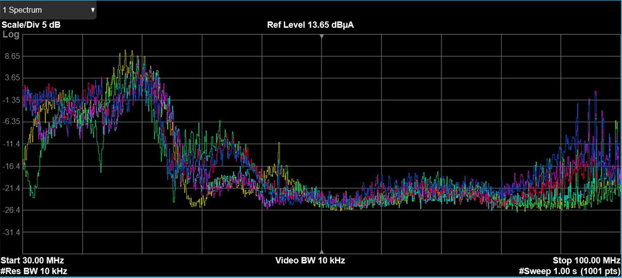
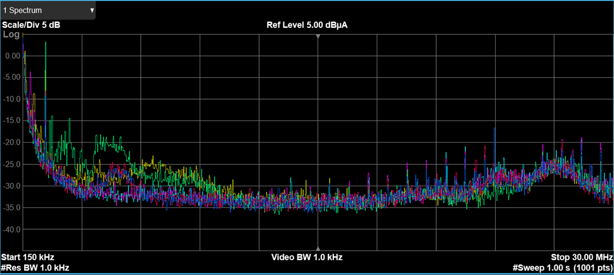
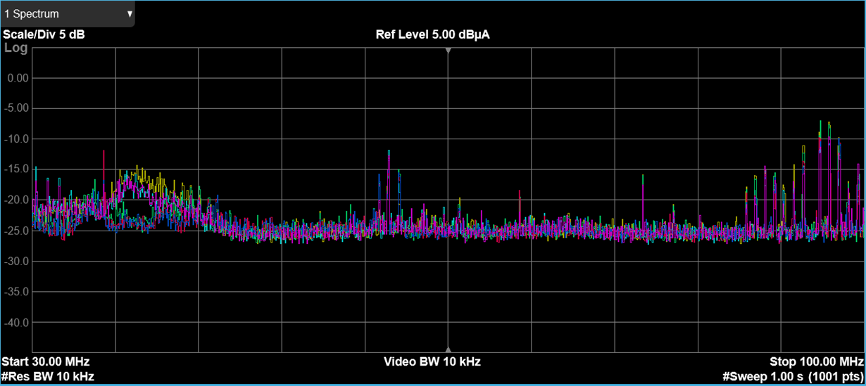
    More background: The audio is not a fully developed feature in our product.  For now we have a product release that does not implement full audio capabilities.  We are currently looking at EMI performance at conducted emissions testing.  After a thorough investigation it was discovered that the audio circuitry was contributing a lot elevated frequencies in the plots.  

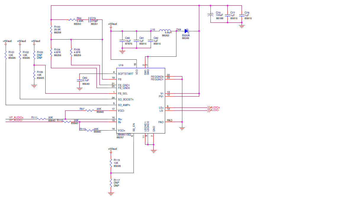
    Schematic:  Please note that our application does not require hi fidelity audio.  This implementation did not implement the three grounds mentioned in the application notes.

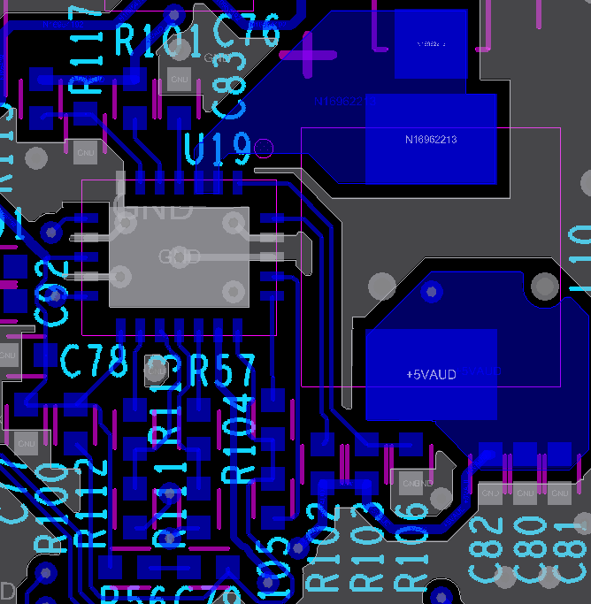
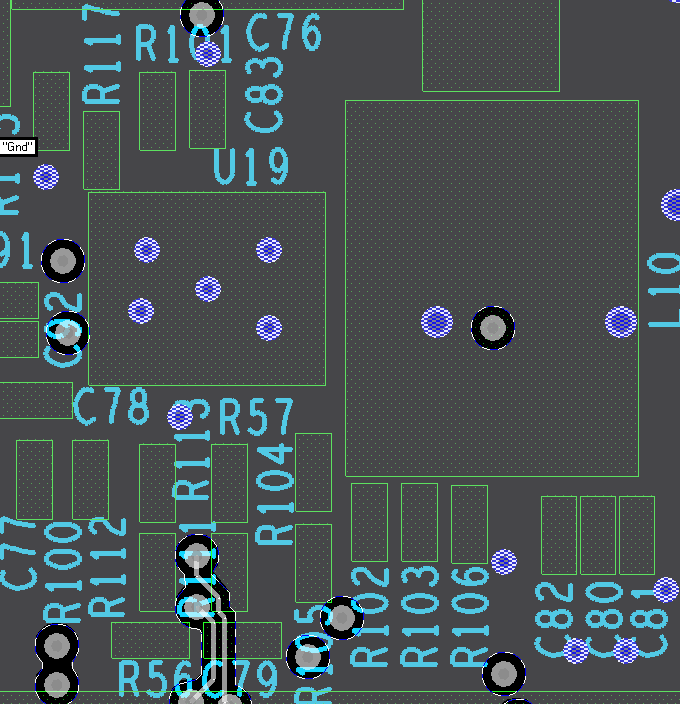
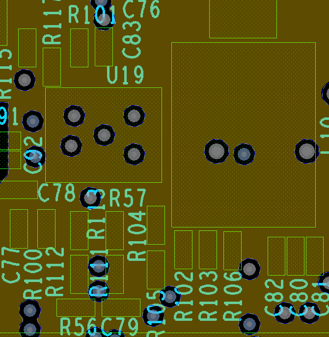
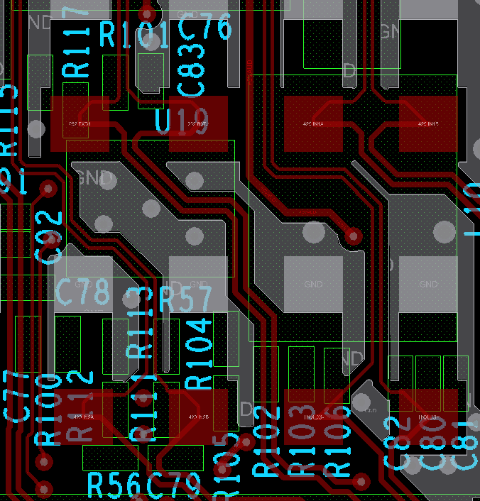
    Layout: As noted the ground is a single net, and perhaps there needs to be more attention made to separating the high current ground from the device ground.  We implemented a four layer board.  LayerTop is the majority of the circuitry, Layer 2 is a ground layer, layer 3 is power, and layer 4 is component backside.  It does seem that a good deal of this noise is coupling from the switching ground, but for our situation right now, we need a partial fix that does not involve board respin.  It does seem that the power layer could be carved up to use for routing the large current GND.  Unfortunately due to schedule constraints we need to just get past this without a board spin.  The plan is to fix this with a future spin.

    Performance:  Here are the spectrum plots for the system with and without audio.

    Evaluation Board: I received the evaluation board last week and I made some measurements.  Channel 1 is the evaluation board and channel 2 is our board.

  • Hi, Andrew,

    Thank you for providing the information about this issue. It is clearer now.

    In order to completely solve this issue, I would recommend to modify the layout for noise immunity. However, if you are looking for a partial fix or provisional solution, I would suggest the following things.

    - Verify if the FB_GND selection changes the noise level. I noticed that you have the option to select FB_GND1 though a pull-up resistor in FB_SEL. Could you try with this other ground path? Also, could you modify the resistor value from 4.87K to 9.31K as suggested in the datasheet?

    - Could you increase the capacitance in the soft-start pin? Please try with 0.25uF steps or similar to check if the noise level is modified.

    - Could you also increase the capacitance level in VDD and use an external power supply (an independent source just for this device)?

    Please let me know if you have questions or comments on this.

    Best regards,
    Luis Fernando Rodríguez S.

  • Luis,

    Thanks for the input.  I'll put this into consideration on our next product spin.  For now we are living with the band-aid fix with a low pass filter on the output.  

    Thanks.