This thread has been locked.

If you have a related question, please click the "Ask a related question" button in the top right corner. The newly created question will be automatically linked to this question.

TLV320ADC6140: How do you access each of the channels for audio recording?

Part Number: TLV320ADC6140

Hello,

I have ported over the TLV320ADC6140 device driver from beagle board to Pocket Beagle. I am currently using a U-Boot overlay to define the pinmux and configuration. I am testing with the TLV320ADC6140 EVM eval module.

Currently, I am able to do arecord to record from channel 1, but if I move the microphone to channel 2-4, no audio is recorded.

I'm thinking the device should load with 4 submodules for each of the channels. Is this correct? Or, should there be multiple instances of the driver?

From looking at the driver code, all 4 channels are enabled by default, register wise.

debian@arm:~$ arecord -f S32_LE -V mono -r 48000 -d 10 -c 1 --dump-hw-params /home/debian/audio_test/tes
t-mic.wav
Recording WAVE '/home/debian/audio_test/test-mic.wav' : Signed 32 bit Little Endian, Rate 48000 Hz, Mono
HW Params of device "default":
--------------------
ACCESS: MMAP_INTERLEAVED MMAP_NONINTERLEAVED MMAP_COMPLEX RW_INTERLEAVED RW_NONINTERLEAVED
FORMAT: S8 U8 S16_LE S16_BE U16_LE U16_BE S24_LE S24_BE U24_LE U24_BE S32_LE S32_BE U32_LE U32_BE FLOAT_LE FLOAT_BE FLOAT64_LE FLOAT64_BE MU_LAW A_LAW IMA_ADPCM S20_LE S20_BE U20_LE U20_BE S24_3LE S24_3BE U24_3LE U24_3BE S20_3LE S20_3BE U20_3LE U20_3BE S18_3LE S18_3BE U18_3LE U18_3BE
SUBFORMAT: STD
SAMPLE_BITS: [4 64]
FRAME_BITS: [4 640000]
CHANNELS: [1 10000]
RATE: [4000 4294967295)
PERIOD_TIME: (1333 341334)
PERIOD_SIZE: (5 1466018367)
PERIOD_BYTES: (2 4294967295)
PERIODS: (0 586406202)
BUFFER_TIME: [1 4294967295]
BUFFER_SIZE: [10 2932031006]
BUFFER_BYTES: [5 4294967295]
TICK_TIME: ALL
--------------------

debian@arm:~$ cat /proc/asound/card0/pcm0c/sub0/info
card: 0
device: 0
subdevice: 0
stream: CAPTURE
id: davinci-mcasp.0-tlv320adcx140-codec tlv320adcx140-codec-0
name: davinci-mcasp.0-tlv320adcx140-codec tlv320adcx140-codec-0
subname: subdevice #0
class: 0
subclass: 0
subdevices_count: 1
subdevices_avail: 1

  • We have some more digital experts that may have some additional comments, but can you confirm that you've physically wired the microphone from CH1 to the CH2-4 channels?  It's only routed to CH1 on the EVM by default. Another option would be to connect a line-input source to CH2-4 terminal blocks to see if you get any information.

  • Hey Collin,

    What do you mean the EVM is only routed to channel 1?

    I have tested the onboard mic, which works. I have disabled the onboard mic by removing jumpers 14, 15, and 16, then plugged in my own microphone, and that works as well.

    When i move the +, ground, and - pins of the mic from channel 1 to in2, in3, or in4, there is no audio out.

  • Hi Bob,

    Thank you for the quick reply, and this confirms what we were looking to verify that you'd connected a known source to those inputs.  The comment was only to confirm that the EVM only has a microphone connected to CH1 and it would have had to be manually externally connected to the other inputs if that was the goal.

    I'm assuming so, but would also like to verify that you've connected the MICBIAS output to the microphones so it's properly powered when connected to the Ch2/3/4 inputs.

  • Hello again,

    Oh, yes I have an external mic, which is soldered to mic bias. I don't remove the mic bias, only move +, -, and ground from the IN1 terminal block to IN2 terminal block.

    Also, my amixer settings have the volume up on all 8 digital channels and the mic gains are at 100%.

    The settings for channel 1, which work, have been duplicated across to all other channels.

    Are there supposed to be 4 sub-devices listed when you do arecord -l? I only see 1

  • Bob,

    The linux driver enables all the channel and only requires one instance. However, the arecord command has only one channel indicated. Try the record command with four channels:

    arecord -f S32_LE -V mono -r 48000 -d 10 -c 4 --dump-hw-params /home/debian/audio_test/test-mic.wav

    Note that the latest version of the driver is here:

    https://git.ti.com/gitweb?p=ti-analog-linux-kernel/dmurphy-analog.git;a=shortlog;h=refs/heads/tlv320adcx140_upstream

    Best regards,

      Pedro

  • Hey Pedro,

    I tried the command with "-c 4" as a flag as well as every number all the way up to 32, no luck.

    I noticed that all the channels are enable by default as well "{ ADCX140_IN_CH_EN, 0xf0 },", so i'm not sure why i'm not able to access 2-4..

    Is the driver supposed to load with 4 sub devices?

    Also, i'm not able to access those bitbucket repositories. The web site shows that "the IP address cannot be found". Do you have another link? The link i'm using for the driver is:

    https://git.ti.com/gitweb?p=ti-analog-linux-kernel/dmurphy-analog.git;a=shortlog;h=refs/heads/tlv320adcx140_upstream

  • here is a copy of my dts so far. Everything works but I don't see multiple sub devices, if sub devices are to be expected. I am loading this a U-Boot overlay so it is easier to develop, without the need to rebuild the kernel every time I want to test.

    /dts-v1/;
    /plugin/;
    
    #include <dt-bindings/gpio/gpio.h>
    #include <dt-bindings/pinctrl/am33xx.h>
    
    / {
            /*
             * Helper to show loaded overlays under: /proc/device-tree/chosen/overlays/
             */
            fragment@0 {
                    target-path="/";
                    __overlay__ {
    
                            chosen {
                                    overlays {
                                            PB-I2C1-TLV320ADC6140 = __TIMESTAMP__;
                                    };
                            };
                    };
            };
    
            #if 0
            /*
             * Free up the pins used by the cape from the pinmux helpers.
             */
            fragment@1 {
                    target = <&ocp>;
                    __overlay__ {
    
    			P2_34_pinmux { status = "disabled"; };  // SHDNz
    
                            P1_29_pinmux { status = "disabled"; };  // mcasp0_ahclkx
                            P1_33_pinmux { status = "disabled"; };  // mcasp0_fsx
                            P1_36_pinmux { status = "disabled"; };  // mcasp0_aclkx
                            P2_30_pinmux { status = "disabled"; };  // mcasp0_axr2
                            P2_32_pinmux { status = "disabled"; };  // mcasp0_axr0
                    };
            };
            #endif
    
            fragment@2 {
                    target = <&am33xx_pinmux>;
                    __overlay__ {
    
    			tlv320adc6140_default: tlv320adc6140_default {
    				pinctrl-single,pins = <
    					//SHDNz
    					AM33XX_IOPAD(0x9a4, PIN_OUTPUT_PULLUP | MUX_MODE7 ) // mcasp0_fsr.gpio3[19] P2_34
    				>;
    			};
    
                            pinmux_P1_29_default_pin {
                                    pinctrl-single,pins = <
                                            // mcasp0_ahclkx.mcasp0_ahclkx
                                            AM33XX_IOPAD(0x09AC, PIN_OUTPUT_PULLDOWN | INPUT_EN | MUX_MODE0)
                                    >;
                            };
    
                            pinmux_P1_33_default_pin {
                                    pinctrl-single,pins = <
                                            // mcasp0_fsx.mcasp0_fsx
                                            AM33XX_IOPAD(0x0994, PIN_OUTPUT_PULLDOWN | INPUT_EN | MUX_MODE0)
                                    >;
                            };
    
                            pinmux_P1_36_default_pin {
                                    pinctrl-single,pins = <
                                            // mcasp0_aclkx.mcasp0_aclkx
                                            AM33XX_IOPAD(0x0990, PIN_OUTPUT_PULLDOWN | INPUT_EN | MUX_MODE0)
                                    >;
                            };
    
    			//Clock enable
                            pinmux_P2_28_default_pin {
                                    pinctrl-single,pins = <
                                            // mcasp0_axr1.gpio3_20
                                            AM33XX_IOPAD(0x09a8, PIN_OUTPUT | INPUT_EN | MUX_MODE7)
                                    >;
                            };
    
    			pinmux_P2_30_default_pin {
                                    pinctrl-single,pins = <
                                            // mcasp0_ahclkr.mcasp0_axr2
                                            AM33XX_IOPAD(0x099C, PIN_OUTPUT_PULLDOWN | INPUT_EN | MUX_MODE2)
                                    >;
                            };
    
    			//DOUT
                            pinmux_P2_32_default_pin {
                                    pinctrl-single,pins = <
                                            // mcasp0_axr0.mcasp0_axr0
                                            AM33XX_IOPAD(0x998, PIN_INPUT | MUX_MODE0)
                                    >;
                            };
                    };
            };
    
            fragment@3 {
                    target-path="/";
                    __overlay__ {
    
    			clk_mcasp0_fixed: clk_mcasp0_fixed {
    				#clock-cells = <0>;
    				compatible = "fixed-clock";
    				clock-frequency = <24576000>; //MCLK Frequency
    			};
    
    			clk_mcasp0: clk_mcasp0 {
    				#clock-cells = <0>;
    				compatible = "gpio-gate-clock";
    				clocks = <&clk_mcasp0_fixed>;
    				enable-gpios = <&gpio3 20 0>; //Pocket Beagle Clock Enable
    			};
    
                            sound {
                                    compatible = "simple-audio-card";
                                    simple-audio-card,name = "TLV320ADCx140 Audio";
                                    simple-audio-card,widgets =
                                            "Microphone", 	"Mic Jack";
                                    simple-audio-card,routing =
                                            "MIC1P",	"Mic Jack",
    					"MIC1P",   	"Mic Jack";
                                    simple-audio-card,format = "i2s";
                                    simple-audio-card,bitclock-master = <&sound_master>;
                                    simple-audio-card,frame-master = <&sound_master>;
    
                                    sound_master: simple-audio-card,cpu {
                                            sound-dai = <&mcasp0>;
    					system-clock-direction-out;
    					clocks = <&clk_mcasp0>;
                                    };
    
                                    simple-audio-card,codec {
                                            sound-dai = <&tlv320adc6140>;
                                    };
                            };
                    };
            };
    
            fragment@4 {
                    target = <&i2c1>;
                    __overlay__ {
                            clock-frequency = <100000>;
                            status = "okay";
    
                            tlv320adc6140: tlv320adc6140@4c {
    				status = "okay";
                                    #sound-dai-cells = <0>;
                                    compatible = "ti,tlv320adc6140";
                                    reg = <0x4c>;
    				ti,mic-bias-source = <6>;
    				ti,use-internal-areg;
    
    				pinctrl-names = "default";
    				pinctrl-0 = <&tlv320adc6140_default>;
                            };
                    };
            };
    
            fragment@5 {
                    target = <&mcasp0>;
                    __overlay__ {
                            #sound-dai-cells = <0>;
                            status = "okay";
                            op-mode = <0>;  // MCASP_IIS_MODE
                            tdm-slots = <2>;
                            serial-dir = <  /* 0: INACTIVE, 1: TX, 2: RX */
    					//<AXR0, AXR1, AXR2, AXR3>
    					2 1 0 0
                                    >;
    
                            tx-num-evt = <32>;
                            rx-num-evt = <32>;
                    };
            };
    };
  • Bob,

    Sorry, I posted the wrong link and have now corrected it. It is the same website you got the driver.

    FYI, there is a device tree binding example here for beagle bone black:

    https://git.ti.com/gitweb?p=ti-analog-linux-kernel/dmurphy-analog.git;a=commit;h=3fc068a34a591d818467da60e06d777b8c7357a9

    The  very limited documentation is here 

    https://git.ti.com/gitweb?p=ti-analog-linux-kernel/dmurphy-analog.git;a=blob;f=Documentation/devicetree/bindings/sound/tlv320adcx140.yaml;h=1433ff62b14f0264ae5278d40a612da8a82ad718;hb=47d53a01e1835c56eec2f301b93156c494f3e068

    Let me check with the driver developer for more input on your issue.

    Best regards,
    Pedro

  • Thanks Pedro. Yah i based the DTS pretty much off of dan murphy's DTS. Thanks again for the help.

  • Bob,

    Have you used alsamixer to ensure the other channels are not muted and on?

    Best regards,
    Pedro

  • Hello Pedro

    Here are my amixer settings. I have all the digital out volume at 79% and mic gain at 100%. I didn't see an option to mute channels in this driver.

    Simple mixer control 'AGC Max Gain',0
      Capabilities: volume volume-joined
      Playback channels: Mono
      Capture channels: Mono
      Limits: 0 - 13
      Mono: 7 [54%]
    Simple mixer control 'AGC Threshold',0
      Capabilities: volume volume-joined
      Playback channels: Mono
      Capture channels: Mono
      Limits: 0 - 15
      Mono: 14 [93%]
    Simple mixer control 'Analog CH1 Mic Gain',0
      Capabilities: volume volume-joined
      Playback channels: Mono
      Capture channels: Mono
      Limits: 0 - 42
      Mono: 42 [100%] [42.00dB]
    Simple mixer control 'Analog CH2 Mic Gain',0
      Capabilities: volume volume-joined
      Playback channels: Mono
      Capture channels: Mono
      Limits: 0 - 42
      Mono: 42 [100%] [42.00dB]
    Simple mixer control 'Analog CH3 Mic Gain',0
      Capabilities: volume volume-joined
      Playback channels: Mono
      Capture channels: Mono
      Limits: 0 - 42
      Mono: 42 [100%] [42.00dB]
    Simple mixer control 'Analog CH4 Mic Gain',0
      Capabilities: volume volume-joined
      Playback channels: Mono
      Capture channels: Mono
      Limits: 0 - 42
      Mono: 42 [100%] [42.00dB]
    Simple mixer control 'CH1_ASI_EN',0
      Capabilities: pswitch pswitch-joined
      Playback channels: Mono
      Mono: Playback [on]
    Simple mixer control 'CH1_DRE_EN',0
      Capabilities: pswitch pswitch-joined
      Playback channels: Mono
      Mono: Playback [off]
    Simple mixer control 'CH2_ASI_EN',0
      Capabilities: pswitch pswitch-joined
      Playback channels: Mono
      Mono: Playback [on]
    Simple mixer control 'CH2_DRE_EN',0
      Capabilities: pswitch pswitch-joined
      Playback channels: Mono
      Mono: Playback [off]
    Simple mixer control 'CH3_ASI_EN',0
      Capabilities: pswitch pswitch-joined
      Playback channels: Mono
      Mono: Playback [on]
    Simple mixer control 'CH3_DRE_EN',0
      Capabilities: pswitch pswitch-joined
      Playback channels: Mono
      Mono: Playback [off]
    Simple mixer control 'CH4_ASI_EN',0
      Capabilities: pswitch pswitch-joined
      Playback channels: Mono
      Mono: Playback [on]
    Simple mixer control 'CH4_DRE_EN',0
      Capabilities: pswitch pswitch-joined
      Playback channels: Mono
      Mono: Playback [off]
    Simple mixer control 'DRE Max Gain',0
      Capabilities: volume volume-joined
      Playback channels: Mono
      Capture channels: Mono
      Limits: 0 - 12
      Mono: 11 [92%]
    Simple mixer control 'DRE Threshold',0
      Capabilities: volume volume-joined
      Playback channels: Mono
      Capture channels: Mono
      Limits: 0 - 9
      Mono: 7 [78%]
    Simple mixer control 'DRE_ENABLE',0
      Capabilities: pswitch pswitch-joined
      Playback channels: Mono
      Mono: Playback [off]
    Simple mixer control 'Decimation Filter',0
      Capabilities: enum
      Items: 'Linear Phase' 'Low Latency' 'Ultra-low Latency'
      Item0: 'Linear Phase'
    Simple mixer control 'Digital CH1 Out',0
      Capabilities: volume volume-joined
      Playback channels: Mono
      Capture channels: Mono
      Limits: 0 - 255
      Mono: 169 [66%] [-15.50dB]
    Simple mixer control 'Digital CH2 Out',0
      Capabilities: volume volume-joined
      Playback channels: Mono
      Capture channels: Mono
      Limits: 0 - 255
      Mono: 201 [79%] [0.50dB]
    Simple mixer control 'Digital CH3 Out',0
      Capabilities: volume volume-joined
      Playback channels: Mono
      Capture channels: Mono
      Limits: 0 - 255
      Mono: 201 [79%] [0.50dB]
    Simple mixer control 'Digital CH4 Out',0
      Capabilities: volume volume-joined
      Playback channels: Mono
      Capture channels: Mono
      Limits: 0 - 255
      Mono: 201 [79%] [0.50dB]
    Simple mixer control 'Digital CH5 Out',0
      Capabilities: volume volume-joined
      Playback channels: Mono
      Capture channels: Mono
      Limits: 0 - 255
      Mono: 201 [79%] [0.50dB]
    Simple mixer control 'Digital CH6 Out',0
      Capabilities: volume volume-joined
      Playback channels: Mono
      Capture channels: Mono
      Limits: 0 - 255
      Mono: 201 [79%] [0.50dB]
    Simple mixer control 'Digital CH7 Out',0
      Capabilities: volume volume-joined
      Playback channels: Mono
      Capture channels: Mono
      Limits: 0 - 255
      Mono: 201 [79%] [0.50dB]
    Simple mixer control 'Digital CH8 Out',0
      Capabilities: volume volume-joined
      Playback channels: Mono
      Capture channels: Mono
      Limits: 0 - 255
      Mono: 201 [79%] [0.50dB]
    Simple mixer control 'IN1 Analog Mic Resistor',0
      Capabilities: enum
      Items: '2.5 kOhm' '10 kOhm' '20 kOhm'
      Item0: '2.5 kOhm'
    Simple mixer control 'IN2 Analog Mic Resistor',0
      Capabilities: enum
      Items: '2.5 kOhm' '10 kOhm' '20 kOhm'
      Item0: '2.5 kOhm'
    Simple mixer control 'IN3 Analog Mic Resistor',0
      Capabilities: enum
      Items: '2.5 kOhm' '10 kOhm' '20 kOhm'
      Item0: '2.5 kOhm'
    Simple mixer control 'IN4 Analog Mic Resistor',0
      Capabilities: enum
      Items: '2.5 kOhm' '10 kOhm' '20 kOhm'
      Item0: '2.5 kOhm'
    Simple mixer control 'MIC1 Analog Mux',0
      Capabilities: enum
      Items: 'Analog' 'Line In'
      Item0: 'Analog'
    Simple mixer control 'MIC1M Input Mux',0
      Capabilities: enum
      Items: 'Analog' 'Line In' 'Digital'
      Item0: 'Analog'
    Simple mixer control 'MIC1P Input Mux',0
      Capabilities: enum
      Items: 'Analog' 'Line In' 'Digital'
      Item0: 'Analog'
    Simple mixer control 'MIC2 Analog Mux',0
      Capabilities: enum
      Items: 'Analog' 'Line In'
      Item0: 'Analog'
    Simple mixer control 'MIC2M Input Mux',0
      Capabilities: enum
      Items: 'Analog' 'Line In' 'Digital'
      Item0: 'Analog'
    Simple mixer control 'MIC2P Input Mux',0
      Capabilities: enum
      Items: 'Analog' 'Line In' 'Digital'
      Item0: 'Analog'
    Simple mixer control 'MIC3 Analog Mux',0
      Capabilities: enum
      Items: 'Analog' 'Line In'
      Item0: 'Analog'
    Simple mixer control 'MIC3M Input Mux',0
      Capabilities: enum
      Items: 'Analog' 'Line In' 'Digital'
      Item0: 'Analog'
    Simple mixer control 'MIC3P Input Mux',0
      Capabilities: enum
      Items: 'Analog' 'Line In' 'Digital'
      Item0: 'Analog'
    Simple mixer control 'MIC4 Analog Mux',0
      Capabilities: enum
      Items: 'Analog' 'Line In'
      Item0: 'Analog'
    Simple mixer control 'MIC4M Input Mux',0
      Capabilities: enum
      Items: 'Analog' 'Line In' 'Digital'
      Item0: 'Analog'
    Simple mixer control 'MIC4P Input Mux',0
      Capabilities: enum
      Items: 'Analog' 'Line In' 'Digital'
      Item0: 'Analog'

  • Bob,

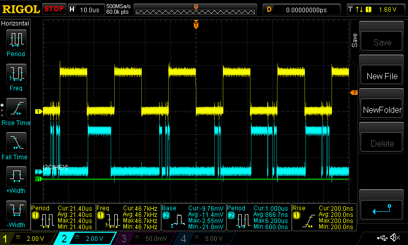
    These settings look fine. Have you checked to see if the TLV320ADC6140 is actually sending the all the channels through the ASI bus into the beagle board? You should be able to probe the DOUT and FSYN lines and see FSYNC followed by four channels of 32-bit data following the FSYNC on DOUT and repeating every FSYNC.

    Best regards,
    Pedro

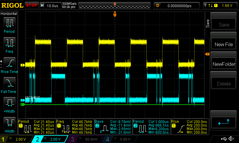
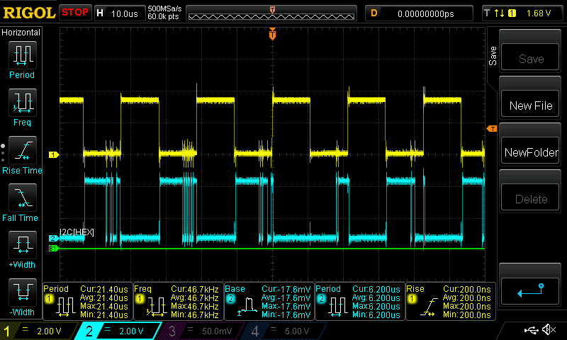
  • Hello again,

    I just probed both fsync and dout.

    arecord -f S32_LE -V mono -r 48000 -d 10 -c 1 /home/debian/audio_test/test-mic.wav

    and

    arecord -f S32_LE -V mono -r 48000 -d 10 -c 4 /home/debian/audio_test/test-mic.wav

    It doesn't look like the -c 4 command is getting through to the codec. Both command output pretty much the same waveform. Yellow = FSYNC, Blue = DOUT

    C1

    C4

  • Shouldn't there be multiple subdevices for each channel for this to work though?

    debian@arm:~$ cat /proc/asound/pcm
    00-00: davinci-mcasp.0-tlv320adcx140-codec tlv320adcx140-codec-0 : davinci-mcasp.0-tlv320adcx140-codec tlv320adcx140-codec-0 : capture 1

    debian@arm:~$ cat /proc/asound/card0/pcm0c/sub0/info
    card: 0
    device: 0
    subdevice: 0
    stream: CAPTURE
    id: davinci-mcasp.0-tlv320adcx140-codec tlv320adcx140-codec-0
    name: davinci-mcasp.0-tlv320adcx140-codec tlv320adcx140-codec-0
    subname: subdevice #0
    class: 0
    subclass: 0
    subdevices_count: 1
    subdevices_avail: 1
  • So i was able to get it working. I changed the tdm-slot to 8 & hardcoded ADCX140_FSYNCINV_BIT.

    It turned out that the positive edge of FSYNC was increasing in duration, with relation to the tdm-slot value. But, the code out of the box was clocking out DOUT on the negative edge, so only 1 channel's worth of data would get clocked out.

    1 last question. I can hardcode the following line "iface_reg1 |= ADCX140_FSYNCINV_BIT;" and it works, but i'd like to not set it from the device tree. All of the other options seem to be able to be set from the device tree, "bitclock-inversion" or "frame-inversion", but i don't see an option for setting ADCX140_FSYNCINV_BIT from the DT.

    static int adcx140_set_dai_fmt(struct snd_soc_dai *codec_dai,
    			       unsigned int fmt)
    {
    	struct snd_soc_component *component = codec_dai->component;
    	struct adcx140_priv *adcx140 = snd_soc_component_get_drvdata(component);
    	u8 iface_reg1 = 0;
    	u8 iface_reg2 = 0;
    
    	/* set master/slave audio interface */
    	switch (fmt & SND_SOC_DAIFMT_MASTER_MASK) {
    	case SND_SOC_DAIFMT_CBM_CFM:
    		iface_reg2 |= ADCX140_BCLK_FSYNC_MASTER;
    		break;
    	case SND_SOC_DAIFMT_CBS_CFS:
    		break;
    	case SND_SOC_DAIFMT_CBS_CFM:
    	case SND_SOC_DAIFMT_CBM_CFS:
    	default:
    		dev_err(component->dev, "Invalid DAI master/slave interface\n");
    		return -EINVAL;
    	}
    
    	
    	printk(KERN_ALERT "fsync bit 3: %d\n", fmt);
    	///iface_reg1 |= ADCX140_FSYNCINV_BIT;
    
    	/* signal polarity */
    	switch (fmt & SND_SOC_DAIFMT_INV_MASK) {
    	case SND_SOC_DAIFMT_NB_IF:
    		iface_reg1 |= ADCX140_FSYNCINV_BIT;
    		break;
    	case SND_SOC_DAIFMT_IB_IF:
    		iface_reg1 |= ADCX140_BCLKINV_BIT | ADCX140_FSYNCINV_BIT;
    		break;
    	case SND_SOC_DAIFMT_IB_NF:
    		iface_reg1 |= ADCX140_BCLKINV_BIT;
    		break;
    	case SND_SOC_DAIFMT_NB_NF:
    		break;
    	default:
    		dev_err(component->dev, "Invalid DAI clock signal polarity\n");
    		return -EINVAL;
    	}

  • oh sorry my mistake. I just found where it is set in soc/soc-core.c

    Frame-inversion & bclk are setting these bits

    /*
             * check "[prefix]bitclock-inversion"
             * check "[prefix]frame-inversion"
             * SND_SOC_DAIFMT_INV_MASK area
             */
            snprintf(prop, sizeof(prop), "%sbitclock-inversion", prefix);
            bit = !!of_get_property(np, prop, NULL);
    
            snprintf(prop, sizeof(prop), "%sframe-inversion", prefix);
            frame = !!of_get_property(np, prop, NULL);
    
            switch ((bit << 4) + frame) {
            case 0x11:
                    format |= SND_SOC_DAIFMT_IB_IF;
                    break;
            case 0x10:
                    format |= SND_SOC_DAIFMT_IB_NF;
                    break;
            case 0x01:
                    format |= SND_SOC_DAIFMT_NB_IF;
                    break;
            default:
                    /* SND_SOC_DAIFMT_NB_NF is default */
                    break;
            }

  • Bob,

    I am not sure I understand your solution or question.

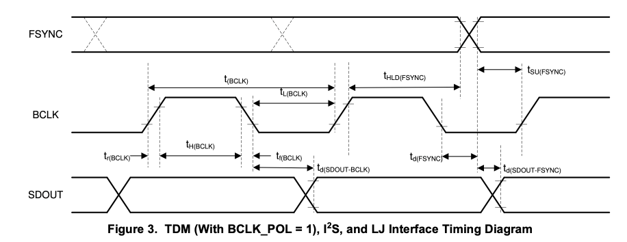
    The timing interface for TLV320ADx14 TDM bus is:

    So the above adcx140_set_dai_fmt routine executed these options in relation to the default values fo the TLV320ADCx140.

    • SND_SOC_DAIFMT_NB_NF  -> normal bit clock and normal frame
    • SND_SOC_DAIFMT_NB_IF  -> normal bit clock and inverted frame
    • SND_SOC_DAIFMT_IB_NF -> normal inverted bit clock and normal frame
    • SND_SOC_DAIFMT_IB_IF  -> normal inverted bit clock and inverted frame

    You could edit the adcx140_set_dai_fmt routine to set the ADCX140_FSYNCINV_BIT as required. 

    best regards,

      Pedro

     
  • Hey again pedro,

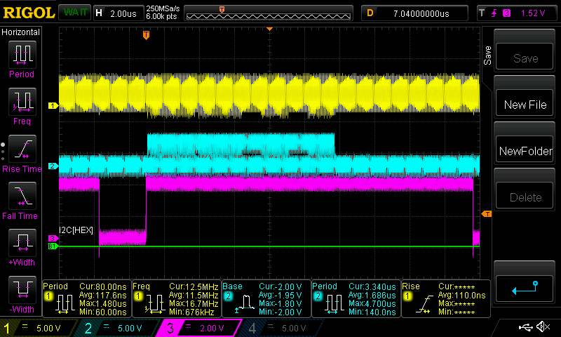
    There is some weirdness going on here. Yah so if i hardcode the FSYNCINV_BIT in adcx140_set_dai_fmt, here is the output: (this output is correctly giving DOUT for each of the 4 channels. (yellow = bclk, blue DOUT, pink FSYNC)

    I verified that the above fmt = 16897 after i hardcode the value.

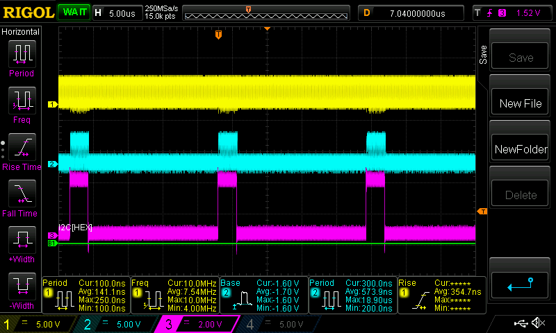
    If you set "simple-audio-card,frame-inversion;" in the device tree, fmt = 16897 as well. So, you would think you don't need to hardcode the value because the same value gets set. But, the scope output looks like this:

    The original output (no bclk, yellow = FSYNC, blue = DOUT). 

    So basically if i increase the TDM-slots value to include multiple channels, instead of the above (last picture), negative edge increasing in duration, the positive edge increases in duration to allow for the TDM slots. So what i want to do is move DOUT to the positive edge. The fsyncinv_bit doesn't seem to do that from the device tree but if i hardcode, it does.

    anyway, i know this is all confusing lol and i'm probably confounding it a bit, but i have a solution so i'm just going to move on with life and go with it. Thanks for all your help!