This thread has been locked.

If you have a related question, please click the "Ask a related question" button in the top right corner. The newly created question will be automatically linked to this question.

LMK03328: How to debug PLL Loss of Lock

Part Number: LMK03328
Other Parts Discussed in Thread: CODELOADER,

Hi Team,

I am having a problem that the PLL Loss of Lock.

It is known that the output of the N divider is stopped.

(Depending on the output of the STATUS0 pin set by R27 [7: 4]=0x4)

The outputs of the R divider and M divider are working normally.

(Similarly, depending on the setting of R27(R28))


How should we debug from here?

WEBENCH data will be attached

webench_design_1113514_25_296579929.pdf

  • Could you share your register settings?
    TICS Pro can save the configuration as .tcs file, which is good for sharing.
    www.ti.com/.../ticspro-sw
    training.ti.com/lmk03328-evm-setup-and-programming-tics-pro-gui
  • Hi Shawn,

    I'm sorry. I only use CodeLoader.

    Is it okay to set up CodeLoder?

    I will attach a file.

    20190110_LMK03328_codeloader.zip

    Best regards.

  • From your Codeload .mac file , you are using PLL1, so PLL2 can be power down by set PLL2_PDN bit.
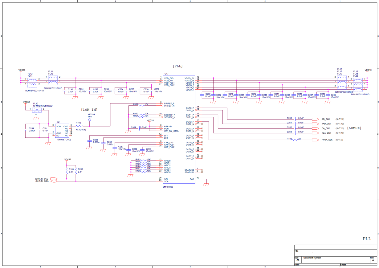
    Make sure schematic design is no problem, refer to LMK03328 EVM user guide.
    Power supply is correct.

    Check "Figure 41. LMK03328 Simplified Programming Flow", make sure default voltage level on GPIO pins and HW_SW_CTRL pin when power up can make LMK03328 enter a correct path.

    10 MHz reference is from PRIREF, which pin is connected, prefer to use P pin?
    Continue to use R27 to read status for "PREREF LOS" . Make sure the reference is detected by LMK03328.
    Otherwise check 10MHz signal waveform, and change setting under "Reference Input Detection".
    R3_mode could choose INT-PLL.
  • Thank you for answering,

    >From your Codeload .mac file , you are using PLL1, so PLL2 can be power down by set PLL2_PDN bit.

    I tried to disable PLL 2 but the output of the N divider has been stopped continuously.

    >Make sure schematic design is no problem, refer to LMK03328 EVM user guide.

    The circuit diagram is a power supply configuration similar to EVM. I could not find a problem.

    The schematic is as follows.

    >Continue to use R27 to read status for "PREREF LOS" . Make sure the reference is detected by LMK03328.

    Since PRIREF Loss of Signal did not become active, it seems that the reference clock has no problem.

    >R3_mode could choose INT-PLL.

    Excuse me, what does R3_mode refer to?
    I will try integer PLL mode.

    Thank you

  • I tried integer PLL mode, but the situation did not change.
    (R66, R69, R117 and R118 registers have been changed.)

    However, changing the setting of R119 [3:2] from 0x0 to 0x01 got the correct frequency.
    (All other settings are settings of the previously sent .mac file.)

    What effect does R119[3:2] setting have on PLL locking?

    Best regards,
  • To set 0x01 is correct in your clock generation case (LBW= 247kHz), because VCO in a closed loop need time to become stable, otherwise device runs in a wrong VCO frequency.

  • Thank you for your reply.
    However, it seems that it is not yet complete, so PLL does not lock at about once in 20 times.
    Is there any other possible factor?
  • 10 MHz TCXO also need time to be stable. It is better to have PDN rising transition later than TCXO stability time. In case TCXO need a long stability time , to increase cap value on PDN pin can delay the rising transition (works as a "reset"), it help LMK03328 lock correctly.
  • I tried integer PLL mode again. Then the clock was output stably.
    (The R65, R66, R69, R117, R118 registers have been changed.)
    I tested it 100 times, and it was stable.

    Thank you for all your assistance.