This thread has been locked.

If you have a related question, please click the "Ask a related question" button in the top right corner. The newly created question will be automatically linked to this question.

WEBENCH® Tools/CDCE62002: Loop filter for cdce62002

Part Number: CDCE62002
Other Parts Discussed in Thread: CDCE62005

Tool/software: WEBENCH® Design Tools

Dear Team:

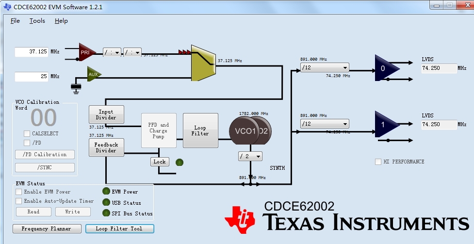
The part is CDCE62002,the input frequency is 37.125MHz(LVCMOS),the output frequency is 74.25MHz(LVDS);

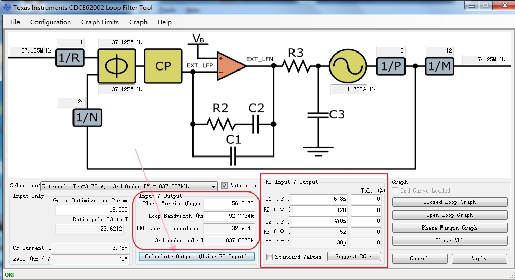
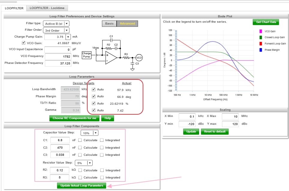
Designing the loop filter,Using the same RC filled into Loop filter Tool and WEBENCH Designer,but the different phase margin、loop bandwidth output,which is the best?

thanks

  • It is better to configure the loop filter for your application by following the procedure from this e2e post. I have pasted the procedure below for reference: https://e2e.ti.com/support/clock-and-timing/f/48/p/769060/2844477#2844477

    Here is a procedure for designing a loop filter using the CDCE62005 EVM GUI:

    1. Press the button "Loop Filter" in CDCE62005 EVM GUI
    2. Input "Phase Margin"  between 45~75 degrees
    3. Select " loop bandwidth" ( normally < Phase Detect Frequency / 15 ). If the input reference clock is noisy, a narrow loop bandwidth could achieve better jitter performance.
    4. Check "Standard Value"
    5. Press the button "Suggest RC's". You may get new RC's value. If there is no exact R or C in hand, select a close value. Then press the button "Calculate Output (Using RC Input)" to update Phase Margin (PM) and Loop Bandwidth (LBW). Make sure that PM and LBW are still in the range of step 1 and 2.

    I hope this information helps.

    Kind regards,
    Lane

  • Hi:

    My confusion is :the same R2、C1、C2 input,but the different output(phase margin、loop bandwidth)between "Loop Filter" in CDCE62002 EVM GUI  and WEBENCH Designer,which one is more accurate?pictures above show the detail parameters

    thanks

  • Thank you for the clarification, I misunderstood your original question.

    The WEBENCH result should match the GUI calculation once you input the VCO Gain.

    Kind regards,
    Lane

  • the output are same once I input the VCO gain

    thank you very much