This thread has been locked.

If you have a related question, please click the "Ask a related question" button in the top right corner. The newly created question will be automatically linked to this question.

LMX2595: PLL not locking with side spurs

Part Number: LMX2595

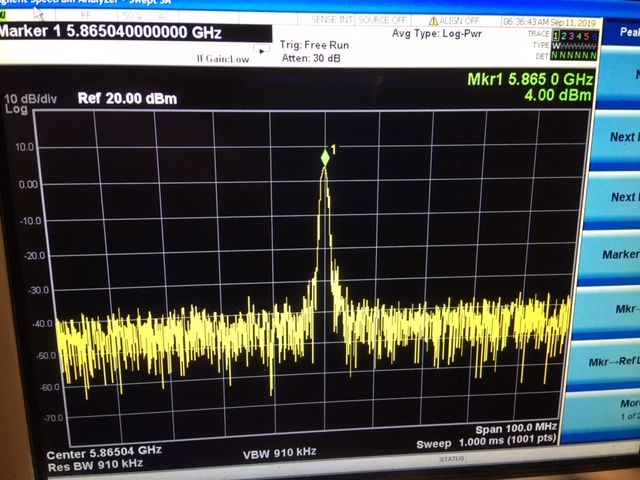
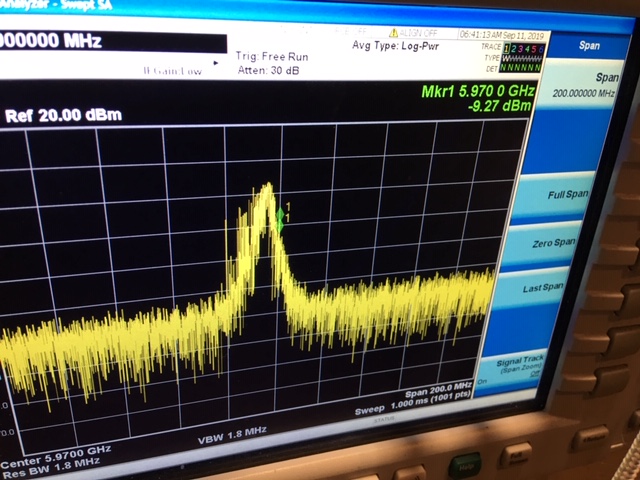
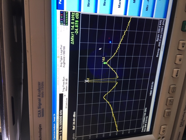
The PLL output does not look as we expect.

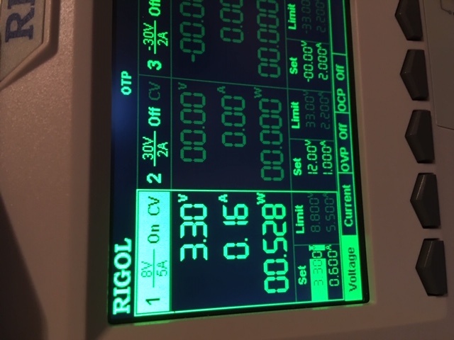
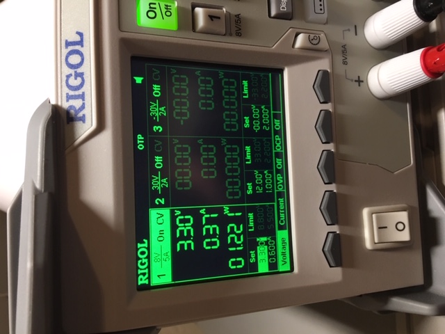
The PLL is reporting that it is locked We are a using a 40 MHz crystal oscillator reference signal in the circuit below. The register values we are using were generated by the PLL API. 

Shouldn't the signal be cleaner? Any feedback on the filter topology we are using would be helpful.

  • Hi Phil,

    What is the output format of the crystal oscillator?

    Pin38 (VregVCO) should not be tied to Vcc, it should be shunt to GND via a 1µF cap.

  • Hi Noel,

    Removing the VregVCO from Vcc did not make any difference.  

    Crystal oscillator is single ended 40 MHz square wave 2.2Vpp.

    Phil

  • Hi Phil,

    Did you measure the reference clock waveform at pin1 of C672? Does it look good?

    Forgot to say, C675 (at the pull-up resistors) should be populated, 100pF or below is sufficient.

    Looks your loop bandwidth is just 14kHz, what is your configuration? Please send me the .tcs file or the screen shot, thanks.

  • Hi Noel,

    Yes, the reference clock waveform at pin1 of C672 looks good. The .tcs file is attached.

    3.6GHz.tcs

  • Hi Phil,

    Any reason to have fpd=2.5MHz? This is a very small fpd but the VCO is at very high freq (14.4GHz). As a result, the N-counter is very big (184320). This will introduce a lot of in-band noise. 

    The simulation result matches with your measurement, the loop bandwidth is reduced to 14.5kHz.

    Furthermore, the settings in the VCO Calibration box (in the PLL page of the GUI) do not match with the fpd. FCAL_LPFD_ADJ and FCAL_HPFD_ADJ should match with your fpd setting.

    Anyway, although your configuration is not perfect, the phase noise should still be good. Can you also try set OSCin doubler to x2, Pre-R=1 such that the fpd is 80MHz? The noise floor should go down and we should be able to see a clean carrier signal. If the carrier is still noisy, I suspect the reference clock is not clean enough.

    BTW, just spotted this out, did you populate R529 (at pin 26)?

  • Hi Noel,

    I'm working with Phil on this issue. I am currently using the 2595EVM board and am not able to get it to lock. I have upload the .tcs file. Please advise.

    Hilary

    2.5GHz_Not_Locking.tcs

  • Hi Noel,

    I'm working with Phil on this issue. I am currently using the 2595EVM board and am not able to get it to lock. I have upload the .tcs file. Please advise.

    In addition, I have loaded the default configuration file, 2018-8-7, which outputs 7 GHz signal. The sequence is as follows, User Controls - RESET, load the default configuration file and toggle FCAL_EN. The LMX2595EVM does not lock. see attached .tcs file defaultConf_2018-8-7.tcs

    Hilary

    3630.2.5GHz_Not_Locking.tcs

  • Hi Hilary,

    All tcs files are good, I don't see any problem.

    With the EVM, please try again with the following sequence.

    1. Open TICS Pro; select LMX2595; Click Default configuration and select Default Mode

    2. Vcc power up the board (can you see 1xx mA current?)

    3. Press Ctrl and L from the keyboard. Alternatively, click USB communications, then Write All Registers in TICS Pro.

    4. You should see it lock, LED lits, current will go up to 4xx mA.

  • Noel,

    I followed your procedure and here are the results I got...

    Here's the power supply on step 2

    Here's the power supply on step 4.

    Here's the signal 

    I did see the lock LED lit up once and here's the signal looked like.

    Here's a picture of the LMX2595EVM, maybe we have something hooked up wrong...

    Please advise.

    Is it possible to do a call?

    Thanks!

    Hilary

  • Hi Hilary,

    You've got the latest EVM that is without the on-board XO. 

    Please provide a clean 100MHz clock source to the OSCinP sma connector. You can use the Reference Pro board as the clock source, only OSCinP is needed, you can leave OSCinM unconnected.

  • Noel,

    Thank you that was our problem! I don't feel too bad, we have two people working this in two locations, 2 EVMs and we both made the same mistake. 

    One more question, our development board has a 40 MHz OSC, can I use a 40 MHz external source rather than the REF PRO?

    Thanks!

    Hilary

  • Hi Hilary,

    Yes, sure.

    Make sure your clock source is able to drive 50Ω load coz there is a 50Ω shunt on OSCinP.