This thread has been locked.

If you have a related question, please click the "Ask a related question" button in the top right corner. The newly created question will be automatically linked to this question.

LMX2594EVM: Generate frequency ramp from 100 MHz to 1.6 GHz

Part Number: LMX2594EVM
Other Parts Discussed in Thread: LMX2594, LMX2491, LMX2572EVM, LMX2572, LMX2492

Hi TI expert, 

We have a LMX2594EVM and we want to use it to generate a linear frequency ramp from 100 MHz to 1.6 GHzIs it possible to generate a continuous and smooth ramp with LMX2594? 

We know the VCO calibration is a limiting factor and we can try to use the "Fully Assist" mode. But I found there would be a 1-2 microsecond gap when VCO core is changing. 

https://e2e.ti.com/support/clock-and-timing/f/48/t/664879?tisearch=e2e-sitesearch&keymatch=lmx2594%25252525252520ramp%25252525252520full%25252525252520assist

e2e.ti.com/.../Fast-frequency-switching-full-assist.pdf

Is it possible that we can do this without this transition time? 

If possible, could you send us an example code that we can load into TICSPRO to generate such a ramp (100 MHz to 1.6 GHz)? We just want to see the code structure. You can use your own calibration and we can do this offline by ourselves.

If LMX2594 cannot generate a smooth ramp, do you have any recommendations from Texas Instrument?
Thanks a lot.
  

  • Hi Joe,

    Linear ramp has very limited start-end freq range, 100MHz to 1.6GHz is not possible. In addition, the ramp function requires that CHDIV remains unchanged during ramp.

    You can always change the VCO frequency by manual SPI programming. As such, there will be lock time involved and as a result, you may not able to get a linear ramp at the end. 

    I don't think there is a very simple way to implement a smooth linear ramp for such a high start-end freq range. 

  • Thanks a lot for your response. Do you have any recommendations from Texas Instrument that can give a linear chirp? The ramp we are looking for is about 1-3 GHz in Bandwidth and should be 10-50 microsecond in length.
    We don't have a constrain on start and stop frequency as long as they are under 10 GHz.
    Thanks in advance.
  • Hi Joe,

    I am afraid you have to use discrete solution, i.e. a PLL + a VCO. 

    We have LMX2491, which is a PLL and is able to support frequency ramping.

  • Hi Noel,
    Thanks for your reply and we will take a look at LMX 2491. I have more questions with LMX2594.
    Suppose if we want to generate a near linear frequency ramp with 1.5 GHz bandwidth (the center frequency can be any frequency below 10 GHz) repeatedly. And we also hope to maximize the repetition rate (in another words, we want to minimize the time to generate each ramp).
    Is it possible that we can achieve the goal in this way?
    First, we calibrate the VCO/CHDIV offline and then slice the whole bandwidth into 20-30 pieces (each bandwidth is about 50-100 MHz and we can generate the ramp without changing CHDIV) and each of them can be covered with at least one VCO/CHDIV pair.
    Then, use the "fully-assist" mode and determine which VCO/CHDIV pair to use.
    Our ramp starts from one VCO/CHDIV pair and this can generate a linear frequency ramp (50 MHz - 200 MHz bandwidth, which depends on the VCO center frequency) without calibration.
    After that, this pair turns off (You mentioned there would be lock time, does this time always exist?) and another pre-calibrated VCO/CHDIV pair is enabled to start a new ramp. And the similar process continues iteratively until it reach the target bandwidth. (See my figure 1)
    If the above plan is realistic, Is it possible to generate ramp function like my figure 2  (We wan to avoid the lock time and we hope there is no time and frequency gap when VOC/CHDIV pair is changed).
    Thanks a lot.
  • In addition, as you mentioned before, the output shape is near square wave at low frequency. What's the minimum frequency that the output approaches a sinusoidal wave (for example, the second harmonic is ~30 dB down)? Do you have any specs for this? When we set the frequency to 500 MHz, the output is still not quite sinusoidal. Is there anything wrong with our device?

    Thanks.

  • Hi Joe,

    The auto ramp of LMX2594 is doing exactly the same thing as shown in your Figure 1. 

    This plot is taken from LMX2572EVM user's guide. LMX2572 uses the same ramp mechanism as LMX2594. In the LMX2572 datasheet, section 8.1.7.2 has more detail explanation on auto ramp. Hopes it help.

    As you may know, the frequency divider is simply a counter. So when the VCO signal gets divided down, the output of the counter is a square wave signal. At higher frequency, because of parasitic and the circuit design, the edge rate of the signal is getting poor and therefore looks more like a sine wave signal. 

    Unfortunately, we don't have test data in this regard.

    We use SiGe BiCMOS to build this part, the fT of this material is very high, it is not surprise to me that the waveform remains square at 500MHz. 

  • From my understanding, the auto ramp of LMX2594 is using auto-calibration mode, which means the lock time is long. What we want to achieve is make the lock time as short as possible, using off-line pre-calibration. Then, what's the typical lock time for each "stop" if we can use "fully-assistant" mode? Using that, I think we can achieve a 2 GHz bandwidth ramp. What's the minimum time needed for this kind of ramp, including segmented ramp time, lock time and everything.

    In addition, is it possible to generate a ramp signal like my second figure?

    You recommended LMX2491. It needs a VCO and an oscillator? As you know, we want to generate a 2 GHz bandwidth linear ramp, do you have any recommendations for VCO and oscillator to achieve this target? Using LMX2492 Evaluation Module, we cannot achieve this, right?

    Thanks a lot.

  • Hi Joe,

    With the auto ramp, the ramp engine will sweep and calibration the frequency automatically. 

    Yes, we can always sweep the output frequency manually by continues SPI programming. With LMX2594, we can use full assist mode to bypass the VCO calibration. The total lock time for a frequency refresh is equal to register programming time + PLL analog lock time. If the SPI rate is 25MHz, then the time taken to program a register is 1µs (24-bit data + 1-bit LE). In worst case scenario, we have to program 6 registers in order to change the frequency in full assist mode. The PLL analog lock time is approx. equal to 4/loop bandwidth. 

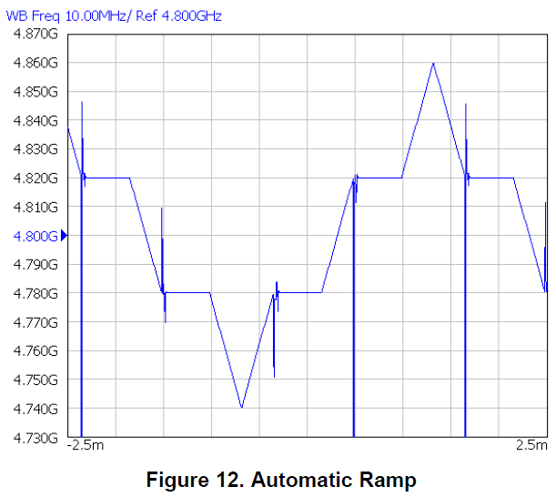
    So even if you use full assist mode, it is still not a perfect linear ramp. It will looks like Figure 12 in the previous post, but the pause time can be minimized.

    Your second figure ramp can only be possible with manual SPI programming.

    I don't think a single VCO can support 2GHz tuning range. With the discrete solution, you may have to use several PLL+VCO to cover the whole tuning range.

  • Hi Noel,

    Thanks for your explanation. We do not need to generate a perfect linear ramp. We just hope it can be as linear as possible. 

    If we use fully-assist mode and pre-calibrate it, what's the maximum time when we move from one frequency to its nearest neighbor frequency (but with different VCO or/and DIV)? If I understand your reply correctly, it should be 1*6 + 4/loop bandwidth? What's the loop bandwidth for LMX2594? I didn't find it in the spec sheet.

    In addition, in LMX2594 spec sheet (page 10), I found 

    What does tVCOCAL mean? 

  • Hi Joe,

    Loop bandwidth is not a device specification, it is a system spec. If you want fast switching time, you should design a wide loop bandwidth loop filter. 

    4/loop bandwidth is a generic equation to estimate the lock time of a PLL. The actual lock time depends on several things. If the delta frequency is small, the lock time is actually smaller than 4/loop bandwidth. 

    TVCOCAL is the VCO calibration time. Without assist = auto-calibration. Please note the calibration time depends on fosc. In the above table, the fosc is 200MHz.