This thread has been locked.

If you have a related question, please click the "Ask a related question" button in the top right corner. The newly created question will be automatically linked to this question.

DS90LV110T: Driving two DS90LV110T simultaneously with minimal lag.

Part Number: DS90LV110T

Hello,

We are designing a PCB and need to have two of these parts essentially in parallel in order to have enough outputs.

What we are struggling with is how to feed two of the parts such that we do not (or lessen as much as possible) any lag between the two sets of inputs.

We would like one part 1/3 of the way down the PCB and the other 2/3 whereas the source is in the upper 1/3.

Any help would be appreciated.

  • Hi Jacques,

    I believe the only ways you can do this are:

    1. Delay the source outputs that are going to the part that is 2/3 down

    2. Make the trace lengths to the part 1/3 of the way down longer by a factor that offsets the difference in distance to the one that is 2/3 down

    Other than that, the best way to ensure to that there is very little skew between the inputs of the parts is to place them an equal distance away from the source. 

    Regards,

    I.K. 

  • So you believe we can drive the signal from the center as opposed to one end?

  • Can you provide a block diagram or illustration for clarification? I am having trouble understanding your follow-up question in relation to your original question. 

    Regards,

    I.K. 

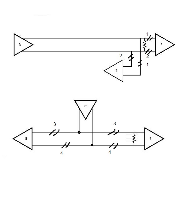
  • Here are some diagrams.

    The top one is what I would expect the configuration to be. This one might have a slight stub effect with the bottom receiver.

    The numbers indicate which legs are the same length.

    The bottom one is what I think you are proposing (i.e. driver in the middle of the "bus").

    What I do not understand with that one is the big stub that will happen with the receiver on the left.

  • Ah, sorry looks like I misunderstood your original post. I thought that your source had two independent outputs for each device, not one output that you were multi-dropping. 

    Your first illustration is the correct way to connect it. In this case I believe the only thing you could do is increase the trace length (e.g. meandering the traces) leading to the receiver that is 1/3 of the way down. However, this would also result in a bigger stub, so you would need to adjust the termination resistor to account for this. This is something you'd have to simulate and/or experiment with. 

    Regards,

    I.K.