This thread has been locked.

If you have a related question, please click the "Ask a related question" button in the top right corner. The newly created question will be automatically linked to this question.

LMK01801: LMK01801 clock output issue

Part Number: LMK01801
We are using following TI clock buffer in our design.
LMK01801 Dual Clock Divider Buffer.
 
We have two queries during testing facing some issue with the clock divider output,
Issue : 1
Clock divider input <= 2.5GHz ,we are getting output as expected(getting divided/2 output upto 1.25GHz ).Above >= 2.5GHz input ,output is not coming.
Issue : 2
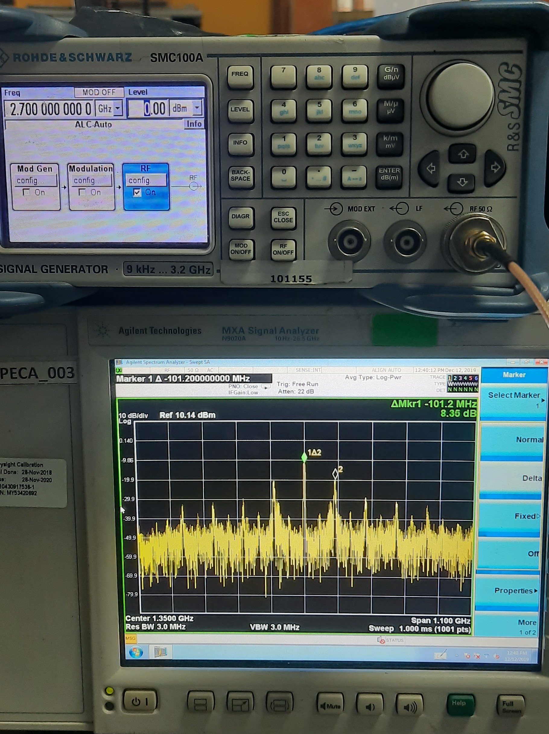
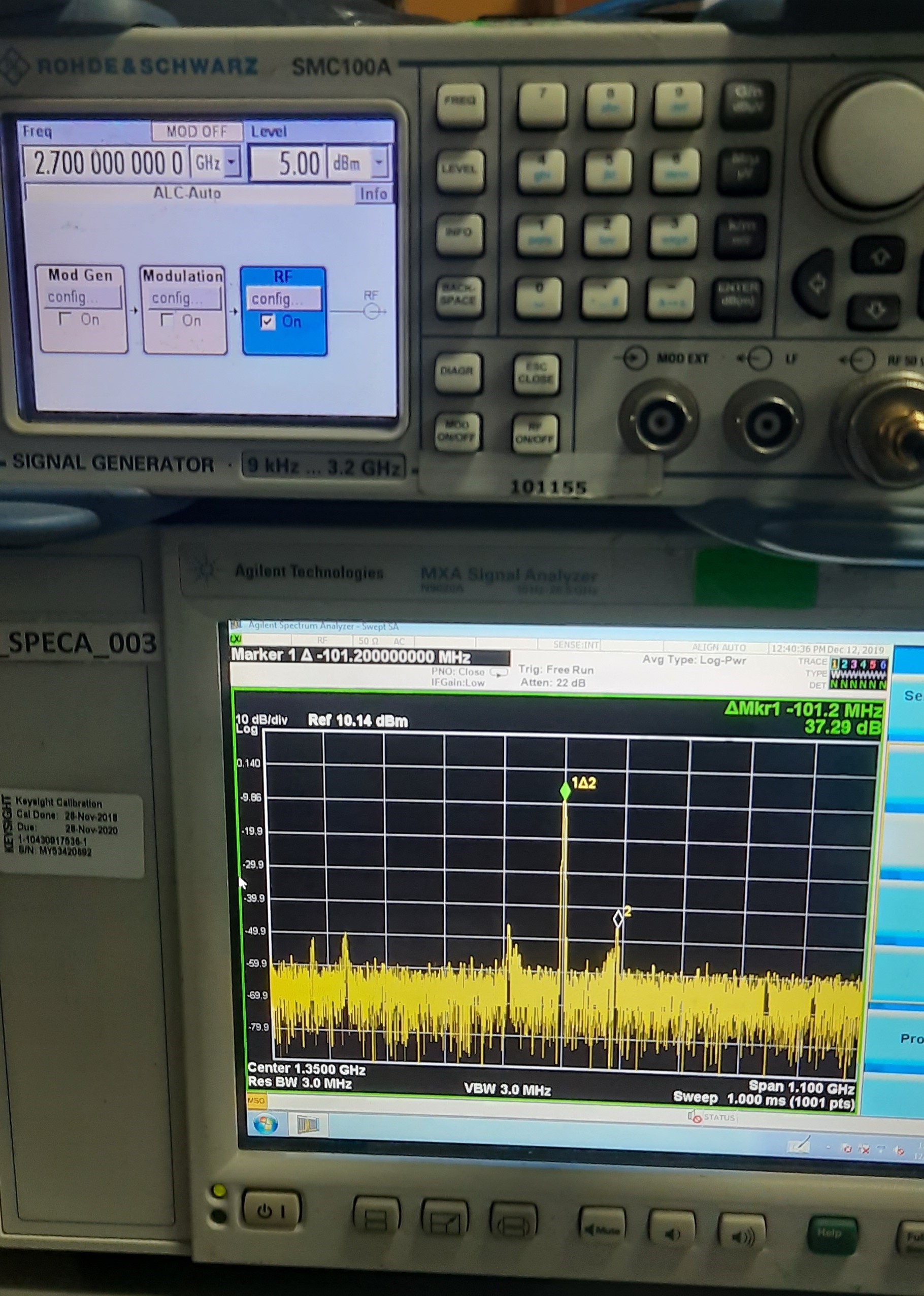
Clock divider output,getting 100MHz,spur with the output.Find the reference captured image.


 Test Condition  :
Input clock frequency : 2.7GHz
Input power level : 0 dBm & +5dBm.
Input signal : Sine wave,Single ended,AC coupling.

Test results  :
Output frequency : 1.35GHz(divide by 2) in CLKOUT4_P, CLKOUT4_N.
Output power : -9dBm
 
 
Kindly suggest solutions to the address the same.
  • Sangeetha,

    Although this device does work up to 3.1 GHz, there are several things that could limit the frequency of the part such as:

    1.  If you have the analog delays on, this limits the frequency

    2. The divider works to higher frequency, but there are two dividers.  Make sure that you do the division on the first divider, not the second one.

    As for the spur, I see two possibilities

    1.  If you have any of the other banks running, make sure that this is not some sort of crosstalk product.  For instance, if one output is at 400 MHz and another is at 500 MHz, you can get 100 MHz spur = GCD(500 Mhz, 400 MHz).

    2.  Looking at the plot, this looks sort of dirty and maybe it is not exactly at 100 MHz.  If you are pushing the divider beyind the spec it is designed for (it says 1.6 GHz if you are using the 2nd divider), then the divider can reach a point where it starts skipping rising edges, making an effect that looks like spurs.  Now this only applies if you are violating the spec and trying to push the 2nd divider to 2.7 GHz input.  If you divide by the first divider, it should work to 3.1 GHz.

    Regards,
    Dean

  • Dear Banerjee,,

    Thnk you for your reply.

    These are the observation we are noticed during testing.

    1.  If you have the analog delays on, this limits the frequency,

    Observation : It is having net path length of 2471.9698 MIL,with FR-4 dielectric material.

    2. The divider works to higher frequency, but there are two dividers.  Make sure that you do the division on the first divider, not the second one.

    Observation : I am using divider in Pin control mode.

    As for the spur, I see two possibilities

    1.  If you have any of the other banks running, make sure that this is not some sort of crosstalk product.  For instance, if one output is at 400 MHz and another is at 500 MHz, you can get 100 MHz spur = GCD(500 Mhz, 400 MHz).

    Observation :FPGA reference clock is 50MHz .

    2.  Looking at the plot, this looks sort of dirty and maybe it is not exactly at 100 MHz.  If you are pushing the divider beyind the spec it is designed for (it says 1.6 GHz if you are using the 2nd divider), then the divider can reach a point where it starts skipping rising edges, making an effect that looks like spurs.  Now this only applies if you are violating the spec and trying to push the 2nd divider to 2.7 GHz input.  If you divide by the first divider, it should work to 3.1 GHz.

    Observation :Yeah it is 1.25GHz & 1.45GHz spur which is affecting my output frequency is 1.35GHz.


  • Hi Sangeetha,

    For pin controlled mode, I would expect the output to be limited to 1600MHz when the output divider is enabled (or output divider is >1) as the input mux mode is bypass.

    It's not clear what is causing the 100MHz spur. Is it possible this is mixing from the 50MHz FPGA reference clock? Perhaps the traces for these signals are too close on the PCB, causing crosstalk. It could also be an artifact from using the divider at too high of a frequency, as Dean mentioned.

    Kind regards,
    Lane