This thread has been locked.

If you have a related question, please click the "Ask a related question" button in the top right corner. The newly created question will be automatically linked to this question.

CDCE62005 output is not correct

Other Parts Discussed in Thread: CDCE62005

Dear All,

I am using CDCE62005 to generate some frequency in my design.

Reference clock          = 76.8MHz,

OUT0、OUT1 、OUT2   = 122.88MHz,

OUT3 、OUT4          = 38.4MHz,

AUX_OUT              = 61.44MHz.

But I find some problem in my tests.

Case 1:

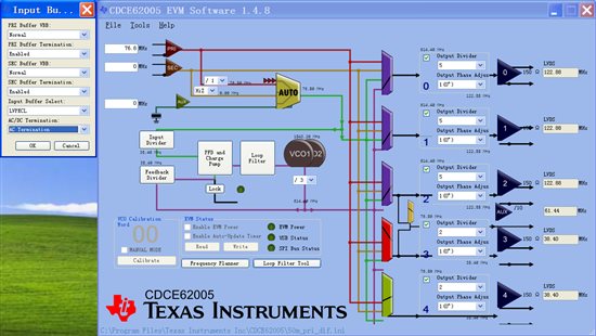
           I use 76.8MHz differential reference clock into primary reference clock (PRI_REF) .The GUI setup see underside picture.

The GUI result is:

REGISTERS

0       EB860320

1       EB860301

2       EB860302

3       EB800003

4       EB800114

5       18040BE5

6       149E0126

7       BD91FDE7

8       80001808


PORTS

0       DD

1       FF

2       DF

3       F9


INPUTS

PRI   76.8

SEC  0

AUX 0


EXTERNAL COMPONENTS

C4    1

R4    1

C5    1


I’m writing this configure value into the registers of CDCE62005 using SPI.

OUT3 and OUT4 is right, so the input clock is alrigh and recognized.

The problem is that PLL is not locked with this configure value.

Why the PLL is not locked? what is the problem?


Case 2:

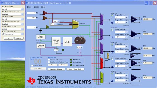
         I use 76.8MHz LVCMOS reference clock into secondary reference clock (SEC_REF) .The GUI setup see underside picture.

The GUI result is:

REGISTERS

0       EB860300

1       EB860321

2       EB860302

3       EB800003

4       EB800114

5       18040A85

6       149E0126

7       BD91FDE7

8       80001808


PORTS

0       DD

1       FF

2       DF

3       F9


INPUTS

PRI   0

SEC  76.8

AUX 0


EXTERNAL COMPONENTS

C4    1

R4    1

C5    1


        I’m writing this configure value into the registers of CDCE62005 using SPI.

        The problem is PLL is locked with these value.But the output of OUT0、OUT1 and OUT2 is 130MHz  —— the expected frequency is 122.88MHz.

It seems the VCO is not working correctly.  What is the problem?

How am I supposed to solve these two problems of case 1 and case 2? Can you help me?

         thank you!!


  • Dear Ping,

    Have you issued a Calibration command after configuring the device? different output frequency than expected is an indication of a missing calibration. I replicated your configuration, without calibration i get similar behavior with unstable locking. after calibration expected behavior is observed with correct output frequency.

    Kind Regards,

    Ahmed

  • Dear Ahmed,

    how did you issued the Calibration command?

    My method is send regsiter value in accordance with the follow sequence:

    EB860320、EB860301、EB860302、EB800003、EB800114、18040BE5、149E0126、BD91FDE7、909E0126、949E0126、80001808.

    The PLL is not locked as normal,and the output frequency is not correct.

    Best Regards.

  • Hi Ping,

    when the output frequency is not correct, then most probably the VCO reached the boundry of tuning range. one reason for that might be that no calibration is done, another reason might be that input is not properly configured.

    so please do the following steps to check

    - make sure you plugged the input source in the correct connector J203 for PRI, or J204 for SEC

    - make sure your input source levels are proper LVCMOS

    - make sure that the right input buffer is selected (LVCMOS). (I noticed that you entered AUX of 0, if you are using the EVM without modifications, you should have 25MHz crystal at AUX, this is just a side note)

    - select the right input divider, and set MUX to the right input (PRI/SEC) manually, to avoid automatic switching without you notice

    - after power up or reset, load your configuration file

    - ensure your configuration is reflected properly on the GUI diagram

    - click on the button (Calibrate), you should see VCO calibration word changing, followed by a stable green Lock detector light.

    I tried both of your configurations, and I don't see issues achieving the lock state.

    just keep in mind that calibration is done automatically at startup, and as the default settings differ than your configuration, the cal values are not suitable for you, after configuration, you have either to do that through the button mentioned, or through the SPI debug bits, or write the values to EEPROM, and do a RESET to issue the normal startup cal.

    Kind Regards,

    Ahmed