This thread has been locked.

If you have a related question, please click the "Ask a related question" button in the top right corner. The newly created question will be automatically linked to this question.

CDCE62005 Reference input and PLL Lock issue

Other Parts Discussed in Thread: CDCE62005

Dear all,

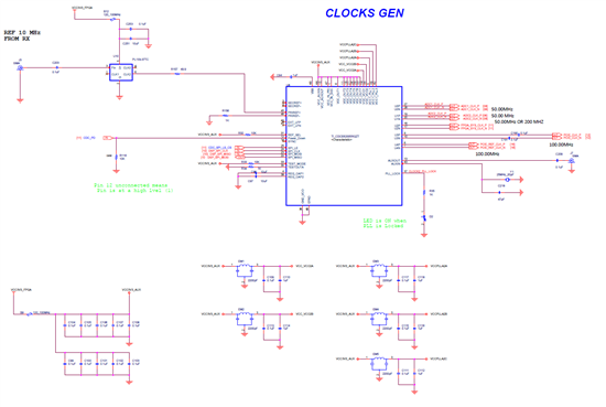
We designed a board with CDCE62005 as shown in the attached files. our input is 10 MHz sinusoidal that is converted to square using PL133-37TC. We also have on board 25 MHz crystal.

we programmed the CDCE with the attached .ini file. using the CDCE62005 EVM GUI (1.4.8). The problem is that we are not always getting pll lock using the 10 MHz reference. we got lock few times only. we tried "Calibrate" button, but no luck. the other problem is that the AUX is not working too. we tried just to pass the AUX to OUT and we don't see it?

Can you see any problem in the design or the .ini settings?...thank you so much in advance!

Please see attached files.

Regards,

8662.CDCE62005.docx8015.CDCE62005.ini

Murad

  • Hi Murad,

    The schematic in the word document is difficult to read. Can you attach a better image?

    When you click the Calibrate button using the EVM, what VCO calibration word is returned? Note that the EVM features AC coupling caps - your configuration is set so that the bias voltage is set externally (verify this via page 39 of the DS and by measuring the voltage at the device pins).

    Gabe

  • Thank you Gabe for your prompt reply. When we lock, the Calibration value varies...sometimes 15, other times 32.

    We are using the EVM ONLY to program the CDCE62005 on our custom board...we removed the CDCE from the EVM and wired the SPI lines from the R111, R112, R129, and R138 to our board's SPI lines. In this case the coupling is based on our design not the EVM design...I am not sure if my settings are correct for the design below and hope you can help me verifying them...we are hoping to finalize the settings so we can order the CDCEs pre-programmed..

    Another question: if we buy them programmed, do we need to interface with the CDCE (using SPI) once we build the board?

    Regards,

    Murad

  • I posted the picture in the above post but I can't see it...please see attached

  • Hi Murad,

    In your schematic, R157 is set to 50 ohms, where the DS for the PL133-37TC calls for this to be a 30 ohm. Could you look at the waveform at the device?

    Additionally, do you have the part # for the XTAL? The large parallel capacitance you have placed may not allow the XTAL to start. A quick test to see if this is an issue is to remove C218 - the XTAL should oscillate just not at the fundamental frequency.

    Gabe

  • Hello Gabe,

    - I will check the output of the PL133-37TC...I remember seeing it on the scope as a 10 MHz squre but what else should I look for?...I'll send you a picture of the escilloscope

    -Question: what should I configure PRI : "Input Buffer Select", "PRI Buffer Termination" and "AC/DC Termination" in the GUI?

    -The XTAL is 7A25000012 and is based on the one used with C6678 EVM    

    Regards,

    Murad

  • Hi Murad,

    Your input buffer seems to be configured correctly. With your register settings, you have turned off internal terminations which is appropriate for DC coupled LVCMOS. We can further debug this when you send scope plots of the signal.

    Request the motional capacitance of the XTAL from the manufacturer. While this XTAL should be ok, the 47 pF load cap you have placed is too large. Follow the section in the DS for choosing the appropriate load cap.

  • Thanks Gabe for your great feedback.

    I took different captures of the clocks as you suggested. I noticed a difference in the amplitude between when the CDCE is locked and when I just reset it...

    Another concern: I was able to have it locked and store configurations in EEPROM...recycle power and I get lock...then an hour later I lost the Lock and when I read the Registers values, data was corrupted!?...this is related to my previous question: if we buy them programmed, do we need to interface with the CDCE (using SPI) once we build the board?0537.CDCE62005_Reference Input_Captures.docx

  • Hi Murad,

    Can you explain further how the register data was corrupted? If the device EEPROM is programmed, no additional programming should be necessary if the register configurations are valid.

    Gabe

  • Hi Gabe,

    I think the register data get corrupted at startup as follows: once we power the system, EEPROM registers get copied into RAM but we have the SPI lines connected to a level shifter and the inputs to the level shifter are not connected to the appropriate pull ups/downs, the contents of the RAM get corrupted and we lose lock...The system is behaving good now.

    Did you have a chance to look at the document I sent you?. I am glad to know that once we program the CDCE, no further communication is needed, so we can just buy them programmed!

    Regards,

    Murad

  • Hi Gabe, 

    Any word on the clock pictures I sent you!

    Regards, 

    Murad 

  • Hi Murad,

    If data is being corrupted after power up, it could indicate your supply or supply ramps are possibly causing issues. Can you provide a shot of the power supply ramp?

    Gabe

  • Gabe,

    nevermind the eeprom issue...we fixed tgat...my last 2 posts were regarding the reference clock and the pictures you ssked for...could you please look at them and let me know if the reference clock to the cdce is good

    Regards,

    Murad

  • Hi Murad,


    The scope plots you sent looked good and showed minimal reflections. Are you still experiencing loss of lock then?

    Gabe

  • Thank you Gabe,

    Everything is good...appreciate your help!

    Regards,

    Murad