This thread has been locked.

If you have a related question, please click the "Ask a related question" button in the top right corner. The newly created question will be automatically linked to this question.

ADS1299 Lead-off detection

Other Parts Discussed in Thread: ADS1299

Hi,

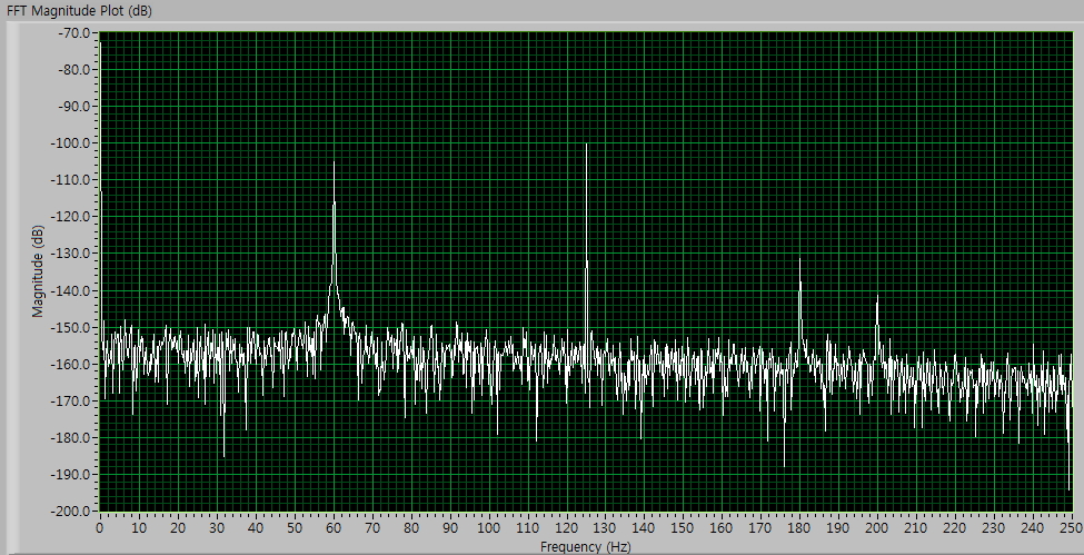
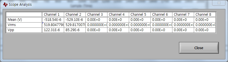
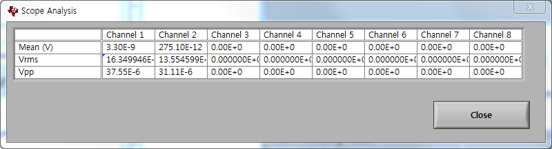
can you please help me with AC lead-off detection. I'm designing mobile EEG device with 24 channels. I need to measure impedance of the electrodes. I'm planing to do this with AC lead-off and current source of 6nA with frequency of the Fdr/4. Can I measure continuously impedance in that way, or I must apply current source externally? Can you also please tell me how can I separately measure impedance of the electrode on non-inverting and inverting input? I need this because my electrode configuration is next: three ADS1299 IC with shorted inverting inputs to one point (reference electrode) and 24 non-inverting inputs (EEG channels). Can I also measure impedance of the electrode connected to the DRL (Driven Right Leg circuit)?

Best regards,

Vojin Ilic

  • Hi Vojin,

    Their are options for the AC lead off excitation signal shown in the LOFF control register (Address = 04h). Including two in band frequency lead off options, 7.8Hz and 31.2Hz, was included for electrode impedance measurement. Fdr/4 you can also use but keep in mind that the -3dB point of this digital filter is Fdr/4 (Figure 26), so the signal will be attenuated internally.

    I do not believe that you have to apply an external current source, the internal options should be capable.

    The AC lead-off method can be used to measure the impedance of the lead, not necessarily the individual electrode. The measurement is done by exciting an AC signal on to the [+] and [-] and then measuring back the amplitude at that frequency. The change in amplitude will tell you how the impedance of the two electrodes, used to create the lead, has changed. If you are tying the [-] to a common point which is not an electrode, then you should be fine monitoring the AC signal amplitude and relating it to the [+] electrode impedance. 

    RLD electrode will not work with the built in AC lead-off signal options. The ADS1299 AC lead-off requires that the channel with the signal is monitored for changes. RLD impedance monitoring must be done externally.

    Regards,

    Tony Calabria

  • Hi Tony,

    thank you very much for your answer.

    I use three IC's ADS1299 and I connect all [-] inputs into one electrode which is called reference electrode in EEG terminology. I need to online measure impedance of all electrodes individually. This means that I must use AC lead-off with current source Fdr/4 because  this is out of band of signal of interest.  Can you please help with impedance measurements, how can I measure impedance of the reference electrode in kohm and how can I measure impedance of the 24 electrode attached to the [+] inputs in kohm. Can I turn-on only current sources on [+] inputs and measure impedance on [+] electrodes, and after that to turn-off this current sources and turn on current source on only one [-] input (because [-] inputs are connected together to the reference electrode) and measure impedance on [-] electrode with respect to the RLD electrode?

    Regards,

    Vojin Ilic

  • Hi Vojic,

    When you saw "Reference Electrode" are you referring to an actual electrode which is connected somewhere on the patient or is it just a term for a common voltage point?

    The design of AC Lead-Off is to measure the differential impedance of the two channels when using one of the two in band AC sources mentioned above (using the fdr/4 is going to be harder due to the attenuation from the digital filter). Like you explained, in the EEG world, the measurements are made referred to a reference electrode. That reference electrode is connected to the (-) channel of all 24 inputs in the system. It is common that we see customers use an external buffer to help with the minor leakage current from the 24 channels. This will isolate the leakage current from the input (-) channel from the reference electrode as well. AC lead off you can just turn on some of the channels using the LOFF control registers. This should be able to give you control to measure individual electrode impedance (assuming you have a buffer on the negative channel). I would have to think about it a little more to be sure. If you do not have a buffer on the negative channel, then you will be reading back the impedance change of the entire lead.

    Regards,

    Tony Calabria

  • Hi Tony,

    when I say  reference electrode, I mean on physical electrode which is connected on the patient. That electrode is on point which is distributed to the 24 [-] inputs of the three ADS1299 IC's. I have also one misunderstanding about LOFF_SENSP and LOFF_SENSN registers. Can I set only a bot LOFFP1? What does it mean for AC lead-off measurement? Will I measure impedance of the [+] side electrode without measuring impedance of the [-] side electrode? I have three IC's with [-] inputs connected to one point which is connected to the electrode on the patient. Can I turn-on only one current source, for example on IC1 I will set bit LOFFM1 and with that configuration to measure differential (sum) impedance of the 24 inputs + ref electrode. I use RLD driver not as reference electrode, but as a null electrode (GND). When I measure EEG potentials, I will measure difference of the [+] electrode - reference elecrode ([-] electrode of the three IC's connected into one point which is called reference electrode and that electrode is connected to the patient) with respect to the RLD electrode (ground), or I must turn on all current sources on all [-] inputs?

    Also can you plese help me with electrode impedance measurement with AC lead-off at frequency Fdr/4. Do I have to multiply FFT value at that frequency with 1.41 (-3dB), or I must to do somethining else. AC lead-off detection at frequencies  at 7.8Hz and 31.2Hz is not good for me, because I have to measure impedance of the electrodes on-line. If I turn on impedance measurement at low frequencies, I can not measure good impedance because EEG signals are in range of 1Hz to 70Hz. Because of that, I must use AC lead-off detection at Fdr/4 frequency. I it is not possible, can you please suggest me some nA current source of TI?

    Regards,

    Vojin Ilic

  • Tony and Vojin,

    Do either of you have any updates on this? I'm working on something similar and would like to know if the ADS1299 can do on-line electrode impedance monitoring. My question is basically the same as Vojin's: although Tony said earlier that the internally generated frequencies would be fine, the datasheet for the ADS1299 says that continuous AC lead-off detection requires an external out-of-band current source or sink. Which is correct, and what part(s) is/are recommended for the external AC current?

    Thanks,

    Graham

  • Hi Graham,

    I've succeed to online measure electrode impedance by using ADS1299 internal current source. You can measure differential impedance by turning on current sources on both inputs of one or more channels, or you can separately measure impedance of electrode on positive input, or on negative input. You must use AC current source, with amplitude of 6nA (because it is small enough and it will not disturb EEG signal) with frequency of Fdr/4. For example is sampling rate is 500Hz, then current source frequency will be 125Hz. When you collect EEG data, you must convert AD data to voltage, and do FFT. In amplitude spectrum of the FFT you will see one component of frequency of 125Hz. When you divide amplitude of that component with amplitude of the current source, it will give you electrode impedance. To try this, you can attach resistors on ADS1299's inputs. I've tried it with fixed resistors of 1Kohm, 10Kohm and 33Kohm. The results is 1.1Kohm, 11Kohm and 30kOhm respectively. The difference of the real impedance and measured impedance is because of the error of the current source amplitude. If you calculate back amplitude of the current source with measured impedance and amplitude in spectrum on frequency of 125Hz, the result will be about 7.5nA. It is small error, and for EEG measurements this error is negligible.

    If you need any help with this, please contact me, and I will help you.

    Best regards,

    Vojin Ilic

  • Vojin,

    Thank you very much for the detailed answer. It seems straightforward but I will certainly contact you if I need any more assistance.

    Graham

  • Hello Vojin,

    what do you mean by amplitude of current current source? Where do you get the information of the Amplitude of the current source?

    Can you post a formula.

    Regards Melanie

  • Hi Vojin,

    Your replies are very helpful for me. I have questions about online impedance measurement.

    In my case, I am designing wireless EEG acquisition device. So, I need online impedance measurement.

    My system consists of 8 channel plus dedicated reference and bias(RLD) electrodes.

    And, I want to set single ended mode for EEG recording.

    In the online impedance measurement, I already understand about setting such as impedance measuring frequency of Fdr/4 and 6nA current source.

    But I need detailed setting information such as LOFFPx/LOFFNx register values and use of reference buffer.

    Because I need to set single ended mode, I am confused about those register values and use of reference buffer.

    The reference buffer is for block of leakage current from electrodes. I think this buffer is necessary.

    However, If I want to use reference buffer, then I think I cannot use current source which located in reference electrode due to block of current flow.

    So, I think I can turn on only LOFFPx registers for measuring the impedance of electrodes. Is it right?

    I have questions about calculation of the impedance values.

    I know I have to use Ohm's law for impedance calculation likes R=V/I

    But, in my case, I think the calculation values seem like wrong.

    For test of online impedance measurement, I used 5k and 10k ohm registers for channel 1 and 2. And, I set 500SPS sampling rate and 6nA current source.

    Using those settings, I got the scope and FFT plots for channel 1.

    I can observe 125Hz frequency signal from those plot.

    My expected voltage values are 120uVp-p for 10k ohm and 60uVp-p for 5k ohm. But, I measured 122.31uVp-p and 85.29uVp-p.

    The first value is correct, but second value seems like wrong value. So, I tried to turn low-pass filter(126Hz), high-pass filter(124Hz) and notch filter for 60Hz.

    Then the voltage values look like something wrong.

    So, my question is how to calculate impedance values. Could you give me detailed information?

  • Hi Mr. Lee,

    about measuring electrode impedance, your measurement are OK. Values for 10K and 5K resistors are OK. 122.31uV and 85.29uV are OK values. Value for 5K resistor are also OK. You must have in mind that tolerance of the current source are +/-20% and also you have a tolerance of the resistor. If you calculate back the current of the current source with this value, you will see that your value is in range of the +/-20% of the 6nA. 

    I built mobile EEG design with 24 channels (three ADS1299 IC). I have 24 electrodes, reference electrode + RLD (right leg driver). I didnt use external buffer for the reference electrode. This is because as you say you cannot use internal current source for impedance measurement. I use current source on all INP inputs and only on one INM input. With this configuration I measure summ impedance on the INP and INM inputs. With your configuration you will measure impedance only on one input (INP). This is also OK, if you dont need information about impedance of the reference electrode.

    If you need any further information, do not hesitate to contact me.

    Regards,

    Vojin

  • This thread was pretty helpful to me as I figured out the impedance-measuring features of the ADS1299.  I wrote up some of my findings...including with some diagrams and pictures to help explain how I worked it out.  If you're interested, you can check it out at:

    http://eeghacker.blogspot.com/2014/04/openbci-measuring-electrode-impedance.html

    Chip

  • ...............................

  • Hey guys,

    although this is an older post I want to continue here, since this topic addresses my issues very well. Let me walk you
    through my setup first.

    I'm using single-ended measurements, meaning all electrodes are connected to the + inputs of the ADS1299, and a common
    reference electrode is routed to the - inputs via the SRB1 pin (without external buffer). The supply is bipolar (+- 2.5V) and the
    internal bias reference is used. All + inputs and the SRB1 input have a anti-aliasing lowpass filter with 5.1kOhm and 4.7nF.

    1) Measuring impedance with AC-lead-off

    Before I start the data acquisition, I want to measure the impedance by using the 7.8Hz/6nA excitation signal, so LOFF=0x01.
    I understand that this is not a very accurate measurement, but it yields sufficient information about the electrode contact
    for me. Keep in mind, that all my + inputs are actual EEG electrodes and all share a common reference electrode via SRB1.
    My first question is, what impedance am I measuring with this setup, if I enable LOFF_SENSP = 0xFF? What setting is needed for
    LOFF_SENSN, since I use the common reference electrode? The MUX setting for every channel is normal electrode (000). I tried
    to verify the impedance measurement by shorting all + inputs with the reference (SRB1) pin and BIAS_OUT pin (just like Chip described it in his excellent eeghacker blog). That means every signal electrode (+ inputs) should have an impedance around 5kOhm (due to the lowpass filter).

    I obtained the following results (channel 1 to 8 from left to right, in kOhm):

    LOFF_SENSP = 0xFF, LOFF_SENSN = 0x00: 5.6, 22.3, 3.0, 17.5, 3.9, 3.9, 6.6, 7.0
    LOFF_SENSP = 0xFF, LOFF_SENSN = 0x01: 5.3, 20.5, 3.2, 16.1, 3.9, 3.9, 6.7, 6.7
    LOFF_SENSP = 0xFF, LOFF_SENSN = 0xFF: 4.9, 17.7, 3.5, 14.0, 3.9, 3.9, 6.7, 6.2

    I can't really figure out the use of LOFF_SENSN for me. Some impedances are in an acceptable range, given the tolerance of the 6nA excitation current, but 22kOhm or 17kOhm are way too much. Also, if I try to get the impedance for every channel seperately, meaning I turn the MUX to OFF for every channel
    but one, and I also only connect that one + input to SRB1 and BIAS_OUT, I get weird results. For example, doing this for
    channel 3 results in 8.3kOhm.

    The way I measure the impedance is getting the rms value of the signal, after it runs through a 6-9Hz bandpass filter, multiplying
    that by sqrt(2) and dividing it by 6nA.

    So what are your thoughts on this? I'm stuck.

    2) Using continuous DC lead-off in combination with Bias drive

    One thing I noticed was that I am not able to simultaneously use the continuous DC lead-off detection and the BIAS drive.
    I used the following configuration:
    BIAS_SENSP: 0x03 (first two electrodes for sensing, bias drive electrode is connected to BIAS_OUT pin)
    BIAS_SENSN: 0x03 (again, what do I do with the SENSN settings, since I use the common reference?)
    CONFIG3: BIAS_MEAS, BIASREF_INT and PD_BIAS set (0xFC, I also use PD_REFBUF)
    CONFIG4: 0x02 (PD_LOFF_COMP set)
    LOFF: 0x00 (DC lead off, 6nA)
    LOFF_SENSP: 0x03 (first two electrodes)
    LOFF_SENSN: 0x03 (again, what do I do with the SENSN settings, since I use the common reference?)

    Now, whenever I start the measurement the LOFF_STATP bits show me immediately that electrode 1 and 2 are off. I assume that
    somehow the bias drive saturates the dc comparators? The bias drive seems to work correctly, since it reduces the DC part of the signal from several mV to <1mV. If I disable the bias drive and leave only the DC lead off activated,
    the lead off detection works just fine. I haven't tested what happens, if I have let's say four electrodes, and only
    the first two are used for BIAS_SENS. Would the lead off detection for the last two electrodes work maybe?

    I appreciate all your comments on this.
    Cheers,
    Andreas

  • Hi there

      I'm working in a hardware with the ads1299, and i want to implement a bias electrode impedance measurement. Can I do it without extra hardware?

  • Hey Leonardo,

    Unfortunately it's impossible to implement real-time bias electrode impedance measurement with the ADS1299. The reason being that the bias lead-off detection uses an internal current source and DC comparator. When the bias amplifier is powered off, the current source will saturate the channel if the Bias electrode is unconnected (i.e. open circuit). If the amplifier is powered on, the current from the current source will sink into the low-impedance output of the amplifier while the voltage will remain stable and the comparator will never trigger. There are, however, approaches using external circuitry that could detect if the Bias electrode is off.

    Regards,
    Brian Pisani