This thread has been locked.

If you have a related question, please click the "Ask a related question" button in the top right corner. The newly created question will be automatically linked to this question.

AFE5809 LVDS outputs interface: deserialization problem

Other Parts Discussed in Thread: AFE5809EVM, HSMC-ADC-BRIDGE, AFE5809

Hi,

I’m working with the AFE5809EVM and I have some issues with LVDS output interface. I’m trying to deserialize 14-bits data of 8-channels configured in test pattern mode with a Cyclone V but I have lots of reading errors.

I’m using an interconnection board HSMC-ADC-Bridge and a development board SocKit as is shown in Fig. 1 and AFE5809EVM is in default configuration (with on-board CMOS clock on). In the FPGA, the SERDES module is configured by an Altera megafunction IP core named ALTLVDS_RX (see Fig. 2 ). This module needs a read clock and the 8-lines of serialized data and performs a 7-bits deserialization. I wrote a program in order to concatenate this 8x7-bits data in 8x14-bits data and to do the bit alignment when AFE5809 generates a sync pattern. Furthermore, I have a second program to check if they are errors in the reading of a ramp pattern.

Fig1.pdf

Fig. 1 - Evaluation boards used

Fig2.pdf

Fig. 2 - schematic of algorithm implemented

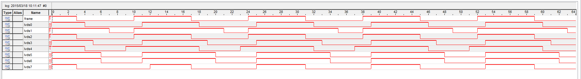
The Fig.3 shown deserialized data when AFE5809 generates a sync pattern. We can see that some channels output data aren’t stable (one or more bits toggle) and we have the good value only for 4 channels (3F80 in hexadecimal). In the Fig. 4, we can see the result of a “good” deserialization for the channel 0 and a “wrong” deserialization for the channel 1 during a ramp pattern. In the Fig. 5, we can see a marker of a goog deserialization (test_nok) which stay at level '0' when there is no problem (it's good for channel 0, 2, 3 and 4).

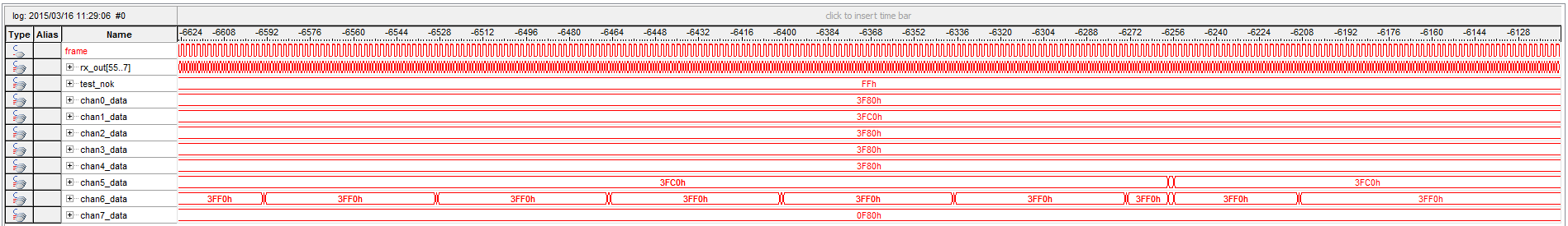
Fig. 3 - 8-chan deserialization of sync pattern

Fig. 4 - 2-chan deserialization of ramp pattern

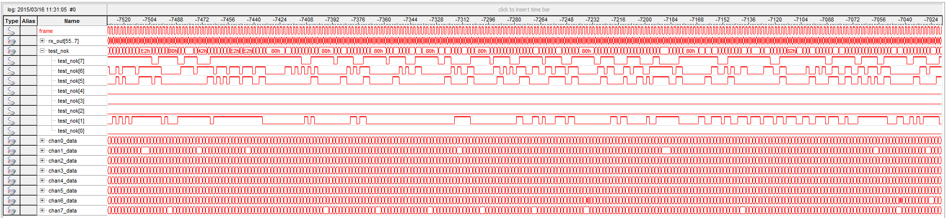
Fig. 5 - test_nok marker with a 8-chan deserialization of ramp pattern

I don’t know where these errors come from but I have tried to visualize the output data lines of AFE5809 and I saw an oscillation in phase with the bit clock (representing by a gray line in the Fig 6.), which may be the source of the problem.

Fig6.pdf

Thank you in advance for your support.

  • Hi Nicolas,

    We received your inquiry regarding the AFE5809 FPGA capture issues.  Thanks for providing  a detailed explanation of the issue you are observing.  Please allow us some time to review your data at which point we will get back to you.

    Thanks,

    Christian

  • Hi Nicolas,
    i'm not familiar with the Cyclone V, but try to enable the differential input termination. Then measure the output data lines of the AFE5809 with a scope again. And also think about timing constraints for your fpga design.
    Regards, Philipp
  • Hi Philipp123 and Christian,

    Thank you for your interest in my problem.

    I have already enabled the differential input termination of Cyclone V. I’m using the LVDS termination as shown below:

    And this is the part of Cyclone V I/O Features datasheet about LVDS termination:

    I can’t show you the exact state of LVDS input because timing requirements of these signals aren’t respected when SignalTap (FPGA signals strobes of Altera) captures it. Despite this, I tried to capture LVDS input with a user-defined clock (dephased by 180°) which is the bit clock multiplied by 2 (each sample is recovered at clock rising edge), here with a sync pattern:

    However, I think that we can’t conclude anything with these inaccurate data.


    In my global design (without SignalTap strobes), I have no timing requirements problems and timing contraints seem respected. Here are my warning messages after compilation and RSKM report of my design (I don’t know if this report is only theoretical or not) with an ideal RCCS of 0.


    Finally, I annotated two SignalTap logs (in case of sync and deskew patterns) to show the problem I encounter. Here, we have the outputs of ALTLVDS_RX (7-bits deserializer) for channels number 0, 1, 6 and 7.

  • Hi,

    as i stated before, try to measure your lvds lanes with an analog oscilloscope an record an eye pattern. If you are sure that your signal integrity is good enough, than you can debug your fpga.

    Unfortunately i can not help you with your altera specific problems (i use xilinx)...

    Best regards, Philipp

  • Hi Philipp,

    It's precisely my problem: I don't have a good enough oscilloscope to measure my lvds lanes and to check the signal integrity.
    I've used a single-ended low band pass oscilloscope on a single lvds data lane in sync mode and I saw a sort of coupling between the bit clock line and the data line but I can't be sure of that because of the poor-quality oscilloscope.
    I think that the fpga part is ok (it's pretty basic) and maybe the problem comes from AFE5809 signals but I can't watch it.

    I'm using three boards which should work out-of-the-box: AFE5809EVM in default configuration, a interconnection card of Texas Instruments (HSMC-ADC-BRIDGE) and a development board for the Cyclone V (SocKit in default configuration too). So for these reasons, I want to know if someone have already seen this kind of results or have an idea to work around my problem...

    Regards,

    Nicolas
  • Ok, this makes it difficult to identify the cause of the problem.
    From my point of views it's a problem related to the clock network and serdes logic in your fpga. Try to use the io delays of your fpga. So you can shift data lanes and bitclock in phase. Perhaps you can tune each lane to be sampled at a stable signal level.
    Regards, Philipp
  • Hi Philipp,

    Thanks for your idea.

    I tried to use input differential buffer with programmable delay chain thanks to ALTIOBUF megafunction of Altera. In my test case, the 50 ns steps delay value is provided from switch inputs. On the other hand, I can't use this with hard SERDES implementation of the Cyclone V and I had to implement my own deserializer circuitry in logic cells. Here is a block diagram of a part of my implementation (I don't like so much block diagrams but it's easy to understand):

    So, I used another PLL to dephase the bit clock (90°) and drive my deserializer, I delayed some input lanes and I compared the results with other "undelayed" lanes which were connected to the hard SERDES implementation. I saw some variations in bits detection when I changed delay values but I have not found a value with good and stable deserialization.

    I also notice that AFE5809 heats a lot during operation and I don't have heat sink on it. Does anyone think that can be a problem ?

    Thanks,

    Nicolas

  • Hi Nicolas,
    as i see, you fed the bitclock through the pll and the frameclock through a differential buffer. This may results in a phase difference between this two clocks through internal routing delays. Try to generate the frame clock with the pll (by division of the bitclock) or generate the bitclock out of the frameclock (by multiplication). If both clocks come out of one pll they should be well aligned.
    Regards, Philipp
  • Hi Philipp,

    I think that the phase between the bit clock and the frame clock is not as critical as the phase between the bit clock and the data. I use the frame clock only to help the bit alignment (the frame clock provides a reference point and I select the right alignment with the help of a sync pattern). However, I also thought of using the frame clock to generate another bit clock but the frame lanes are not routed to drive dedicated clock pins required to be a clock reference for the PLL.

    For now, I'm trying to use an external lower-frequency clock (10MHz) to drive AFE5809 and I'm sharing this clock with the FPGA (I'm using another development board with a Cyclone III which have a sma dedicated clock input). I can add a phase at the AFE5809 clock independently of the FPGA clock. Despite this, it's difficult to find a phase value which allows to have a right 8-chan deserialization (a ramp pattern deserialization without errors): it requires to have a 0.1° phase accuracy !

    I wonder if the chip is operating normally but I don't know how to test without a specific oscilloscope (with differential inputs and a large enough input bandwidth).

    Regards,

    Nicolas