This thread has been locked.

If you have a related question, please click the "Ask a related question" button in the top right corner. The newly created question will be automatically linked to this question.

ads1282-ht: bit toggling in output data

Part Number: ADS1282-HT
Other Parts Discussed in Thread: ADS1282, OPA211-HT, OPA211

Hello,

I have two identical hardware boards, each with 3 ADS1282-HTs.  From one of these ADCs on one board I am getting a bit toggling in the output data seemingly at random.  I connected the input of this misbehaving ADS in parallel with the input of another ADS on the same board, with a 5K resistor across the inputs.  They share the same voltage reference and are programmed with the same script.  I connected a logic analyzer to the data output pins of both and recorded several seconds of data.  When I imported and plotted the data I could see that one ADS exhibits this bit toggle and the other does not.  Here's a plot of the output data:

My assumption at this point is that I have a bad part despite it being brand new.  Replacing the parts will cause us quite a bit of delay.  Is there any other explanation for my observation, or can you confirm this is a bad part?  Thanks,

  • Hi,

    If I understand correctly, you have input the exact same signal to both ADCs and programmed the two devices identically but see the difference in the output. Could you please probe the reference voltages of both ADCs on a scope to ensure one isn't collapsing as well as the power supplies of both ADCs. I recall seeing similar behavior if an ADC's power rail collapses momentarily or if the ADC is current starved.

    Thanks
    Christian
  • Hi Christian,

    Both ADCs are on the same board and share all power rails and the voltage reference in common. That being said I will probe both devices at their supply pins and look for differences. I have a second identical board which doesn't exhibit this behaviour.
  • Hi rsbonini,

    In addition to Christian's comment...

    I might also suggest checking the SCLK signal integrity near the ADC with the bit toggling issue.
    If there is some ringing on the SCLK signal to that ADC, it might register it as an extra clock and cause the data to shift. If you're sharing this SCLK trace with all three ADCs then the "branches" (or stubs) on this PCB trace might be more susceptible to ringing than a normal microstrip trace routed to a single CLK input.

    Best regards,
    Chris

  • I double checked the power supply rails while observing the data output from the ADCs. I did not observe any glitches/dropouts from the V_ref, 3.3V or 5V rails while I did observe many (average ~1/sec) of these 'bit toggle' events in the output data. The 5V supply pin sits at 4.97V and the 3.3V supply pin sits at 3.27V. Absolute max/min for the supply voltages is about +/- 3mV, this variation seems too small to cause voltage under supply or be evidence of a current starved condition.

    I also checked SCLK signal integrity and it looks good. I should add that while the power supplies and voltage reference are shared by all three ADCs, they each have their own dedicated SPI bus including a dedicated SCLK line. I compared the SCLK between all three ADCs and could find no appreciable difference between them.
  • Hi rsbonini,

    To help rule out the possibility of some kind of device-to-device interaction, would it be possible for you to power down the other two ADCs and just collect data from the ADC in question?
    With the other devices in power-down, they won't be loading the reference or supply sources.

    Also, would it be possible for you to share a raw data file of the erroneous output data, and possibly a schematic of your circuit as well? Feel free to email (rather than attach it to the forum) to pa_deltasigma_apps@ti.com.

    Best regards,
    Chris

  • Hi Christopher,

    Powering down the other two ADCs would be tricky with the boards assembled as is, but may be possible.  I have emailed you a copy of the relevant circuit block as well as a spreadsheet with the captured data to the address above.  Thanks,

  • So I went ahead and replaced the ADC this morning but have the same/similair issue.  There is still a bit "toggling" about once a second in the data output however the bit is now in a different position.  Obviously there is something board specific going on.  Any indication of where to look would be greatly appreciated.  Thanks.

  • Hi rsbonini,

    Which op-amp are you using on the front-end? I would suggest trying two things...

    1. Try replacing the op-amp to see if the issue goes away. There might be a popcorn noise issue with the op-amp.

    2. Additionally, I might suggest removing the resistor divider on the 2.5V source and connecting the non-inverting op-amp inputs directly to 2.5V with a 0-Ohm resistor. I'm not sure why you would want to want to divide that voltage down since 2.5 V is exactly mid-supply for the ADS1282.

    The only other thing that is a bit concerning to me is the split analog and digital ground connection...
    If you're only connecting AVSS to DGND only at one point on the PCB, then one or more of the ADS1282 ground connections or digital signals may appear inductive (if the ground bridge is not directly under the ADC or if the digital signals are routed over the ground cutout) and be prone to ground bounce. However, in this case I would expect the problem to appear as additional Gaussian noise in the ADC's output code; not necessarily a changing offset voltage.


    Best regards,
    Chris

  • Hi Chris,

    1. It's the opa211-ht, will look into this.

    2. How would the divider cause the issue I've been seeing?  The divider is there because despite 2.5V being mid supply, it's not the middle of the input range of the ads1282.  The input range is AVSS+0.7V to AVDD-1.25V (datasheet pg.7).

    3. The analog and digital grounds aren't physically split, they're actually the same plane.  The separate symbols in schematic are there as reminders to maintain proper analog/digital routing.

    Thanks for the input, -robert

  • Hi Robert,

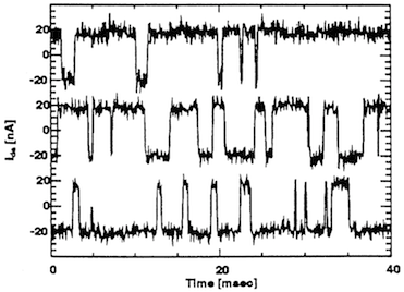
    1. The OPA211 is a bipolar device and what you're seeing looks very much like popcorn or burst noise:

      Reference: 
       

    2. Popcorn noise can be (but is not always) related to a change in the input bias current of the amplifier. The change in offset may be proportional to the equivalent impedance seen on the opamp's input pin. Removing this resistor divider and connecting the opamps directly to 2.5V might help to minimize this error.

      You are correct, the ADS1282 PGA has an input range that is not centered at 2.5 V. I had been thinking about other devices with symmetrical input ranges. However, if you can tolerate the limit on the positive input swing, I would still recommend removing the resistor divider and connecting to 2.5V through a 0-Ohm resistor.
       
       
    3.  OK, then that is not an issue...I'm just used to seeing split ground plane layouts when separate ground symbols are used.


    Best regards,
    Chris

  • Hi,

    Did replacing the op amp fix the issue you were observing?

    If this answers your question, please click the "This resolved my question" button so we can close the thread and add this to our database of searchable archived responses.

    Thanks
    Christian
  • Chris,

    I tried several other tests on the system with no change, however Christian's note about power supplies nagged at at the back of my mind.  I built an entirely new power supply board (PS board and ADC board are connectedcd via header pins) and the problem went away entirely.  When I switched in the old power supply board the problem came back.  Not sure what is wrong with it, but obviously these ADCs can be quite sensitive to power supply issues.  Will keep an eye on this in future.  Thanks all!

  • Hi again,

    If this answers your question, please click the "This resolved my question" button so we can close the thread and add this to our database of searchable archived responses. Otherwise please let us know where you are trying to resolve this problem.

    Thanks
    Christian
  • Hi Robert,

    Okay, thanks for the update!

    I don't know if you are using LC filters on any of your supplies; however, one common issue I have seen in the past is that such filters can either resonate (at the LC-resonator freq) or limit current to the ADC during transient events. Just as a note, most of our ADCs are not designed for inductive supply filters, so I would caution the use of them for noise filtering on either the analog or digital supplies of the ADC.

    Best regards,
    Chris
  • Hi again,

    If this answers your question, please click the "This resolved my question" button so we can close the thread.

    Thanks
    Christian