This thread has been locked.

If you have a related question, please click the "Ask a related question" button in the top right corner. The newly created question will be automatically linked to this question.

ADS7924: Problem in reading 4 channel using I2C

Part Number: ADS7924
Other Parts Discussed in Thread: TM4C129DNCPDT,

Hello friends

I am using ads7924 in my project and i2c is the link between my tm4c129Dncpdt and ADS7924,

I have configured as per the datasheet according to me.

Now the issue is I am getting the first channel value correctly on my i2c and it varies according to the input,but if I do the same thing with my second channel it is nor working.

And when I change my input to channel 1 it is effecting my channel 2 value also since I am reading only 2 channels out of four,

Below is my code on  i2c. Suggest me if anything I am doing is wrong.

/**** ADC init ***/

Adc_Channel_init(0x48,0x00,0x80,1); //awake mode

Adc_Channel_init(0x48,0x12,0x1C,1); //created intrpt

Adc_Channel_init(0x48,0x00,0xC8,1);// manual scan mode

it is in 3 sec cyclic function

ROM_I2CMasterSlaveAddrSet(I2C2_BASE, slave, false);

ROM_I2CMasterDataPut(I2C2_BASE,0x82);

ROM_I2CMasterControl(I2C2_BASE, I2C_MASTER_CMD_BURST_SEND_START);

while(!ROM_I2CMasterBusy(I2C2_BASE));
while(ROM_I2CMasterBusy(I2C2_BASE));


//specify that we are going to read from slave device
ROM_I2CMasterSlaveAddrSet(I2C2_BASE, slave, true);

//send control byte and read from the register we
//specified
ROM_I2CMasterControl(I2C2_BASE, I2C_MASTER_CMD_BURST_RECEIVE_START);

//wait for MCU to finish transaction
while(!ROM_I2CMasterBusy(I2C2_BASE));
while(ROM_I2CMasterBusy(I2C2_BASE));

//return 1st byte pulled from the specified register
data[0] = (uint8_t)ROM_I2CMasterDataGet(I2C2_BASE);

while(ROM_I2CMasterBusy(I2C2_BASE));

ROM_I2CMasterControl(I2C2_BASE, I2C_MASTER_CMD_BURST_RECEIVE_CONT);

//wait for MCU to finish transaction
while(!ROM_I2CMasterBusy(I2C2_BASE));
while(ROM_I2CMasterBusy(I2C2_BASE));

//return 1st byte pulled from the specified register
data[1] = (uint8_t)ROM_I2CMasterDataGet(I2C2_BASE);

while(ROM_I2CMasterBusy(I2C2_BASE));

// ROM_SysCtlDelay(100);

ROM_I2CMasterControl(I2C2_BASE, I2C_MASTER_CMD_BURST_RECEIVE_CONT);

//wait for MCU to finish transaction
while(!ROM_I2CMasterBusy(I2C2_BASE));
while(ROM_I2CMasterBusy(I2C2_BASE));

//return 1st byte pulled from the specified register
data[2] = (uint8_t)ROM_I2CMasterDataGet(I2C2_BASE);

while(ROM_I2CMasterBusy(I2C2_BASE));

ROM_I2CMasterControl(I2C2_BASE, I2C_MASTER_CMD_BURST_RECEIVE_CONT);

//wait for MCU to finish transaction
while(!ROM_I2CMasterBusy(I2C2_BASE));
while(ROM_I2CMasterBusy(I2C2_BASE));

//return 1st byte pulled from the specified register
data[3] = (uint8_t)ROM_I2CMasterDataGet(I2C2_BASE);

while(ROM_I2CMasterBusy(I2C2_BASE));

ROM_I2CMasterControl(I2C2_BASE, I2C_MASTER_CMD_BURST_RECEIVE_CONT);

//wait for MCU to finish transaction
while(!ROM_I2CMasterBusy(I2C2_BASE));
while(ROM_I2CMasterBusy(I2C2_BASE));

//return 1st byte pulled from the specified register
data[4] = (uint8_t)ROM_I2CMasterDataGet(I2C2_BASE);


ROM_I2CMasterControl(I2C2_BASE, I2C_MASTER_CMD_BURST_RECEIVE_CONT);

//wait for MCU to finish transaction
while(!ROM_I2CMasterBusy(I2C2_BASE));
while(ROM_I2CMasterBusy(I2C2_BASE));

//return 1st byte pulled from the specified register
data[5] = (uint8_t)ROM_I2CMasterDataGet(I2C2_BASE);

ROM_I2CMasterControl(I2C2_BASE, I2C_MASTER_CMD_BURST_RECEIVE_CONT);

//wait for MCU to finish transaction
while(!ROM_I2CMasterBusy(I2C2_BASE));
while(ROM_I2CMasterBusy(I2C2_BASE));

//return 1st byte pulled from the specified register
data[6] = (uint8_t)ROM_I2CMasterDataGet(I2C2_BASE);


ROM_I2CMasterControl(I2C2_BASE, I2C_MASTER_CMD_BURST_RECEIVE_FINISH);

//wait for MCU to finish transaction
while(!ROM_I2CMasterBusy(I2C2_BASE));
while(ROM_I2CMasterBusy(I2C2_BASE));

//return 1st byte pulled from the specified register
data[7] = (uint8_t)ROM_I2CMasterDataGet(I2C2_BASE);

UARTprintf("ch1 msb %x lsb %x - ch2 msb %x lsb %x - ch3 msb %x lsb %x - ch4 msb %x lsb %x\r\n",data[0],data[1],data[2],data[3],

data[3],data[4],data[5],data[6],data[7]);


Adc_Channel_init(0x48,0x00,0xC8,1); //for multiple scan

Regards

Harish

  • My question is can I read only 2 channels by using manual scan mode ??

    I am initialising like below

    1) writing 0x80 in address 0x00 to keep in awake mode

    2)Writing 0xC8 in address 0x00 for manual scan mode

    and after that I am reading for every 500msec

    I am reading like this

    for channel 1

    1)Writing 0x82 and reading two values   //since I have incremented the first bit so I am reading 0x02 and 0x03

    2)writing 0xC8 in address 0x00 for manual scan mode

    for channel 2

    1)Writing 0x84 and reading two values   //since I have incremented the first bit so I am reading 0x02 and 0x03

    2)writing 0xC8 in address 0x00 for manual scan mode

    And after giving input to channel 1 I am reading correctly from channel 1 but at the same time if I read 2nd channel it is also giving values.

    And if I give input to 2nd channel it is not reading correctly.

    If I read channels one by one by using auto scan single mode then I can read correctly. But not in multiple scan mode.

    I have checked in the cro I2c communication is working fine but the data's in register is not correct or I am not reading it correctly.

    Can someone plz help me out with this ??

    Regards

    Harish

  • Hi Harish,

    Thank you for your patience. I am looking into this and will get back to you soon.
  • Hi Harish,

    Based on your latest post in which you summarized your code, I have several recommendations:

    1) After placing the device into Awake Mode and then giving the Manual-Scan command, I recommend reading both channels directly. Table 3 on page 26 of the datasheet gives the register address for the channels and figure 33 on page 25 shows how to read multiple registers.

    2) Under your description for reading channel 2, you are writing 0x84 and then 0xC8. There is no valid command for 0x84 (assuming that you are writing this to the Mode Control Register), and may be putting the device into an unknown state.

    3) Manual scan mode converts all of the channels once, but you are providing the command each time you wish to read a single channel. Have you considered using the manual-single mode to only convert a single channel? This would save power as the ADC will not be converting as often.
  • Hi Evan
    Sorry for the late reply

    I have configured my device as manual scan mode and to get multiple readings after reading a scanned values I am reconfiguring it.

    And for reading I am reading 0x82 and follow and 0x84 and follow register which are the register's of channel 1 and channel 2 but the data somehow when I am giving voltage to channel 1 somehow it is affecting the channel 2 and if I give input to channel 2 it is not updating I have checked in cro and it looks fine other then the data which I get back and I have checked in hardware and the input pins it looks fine.

     
    If I want to read 2 channels then how can I use ads7924 in single mode  switching channel using awake mode is not working with me???


    Regards
    Harish

  • Hi Harish,

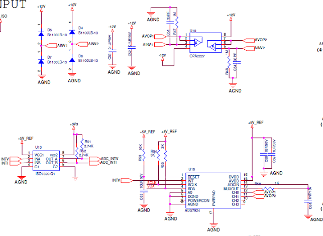
    If possible, can you please share the schematic for your input driver circuit? Because you are seeing values on channel 2 when channel 1 has an input, I suspect this may be a hardware issue.
  • Hi Evan

    Input is taken from opamp which is connected to a connector.

    Regards

    Harish

  • Hi Harish,

    I have two suggestions for you to try:

    1) Place a 0 ohm resistor at R58 (the resistor between MUXOUT and ADCIN), and remove C64.

    2) If #1 does not work, try removing C51 and C54 (in addition to the changes suggested in 1).

    There may be a settling issue at the input of the ADC caused by the RC pair, or switching being coupled back from one channel to the other via C51/54.
  • Hi Evan

    The first method itself worked . I am really thank full to you.

    Regards

    Harish