This thread has been locked.

If you have a related question, please click the "Ask a related question" button in the top right corner. The newly created question will be automatically linked to this question.

ADC12DJ3200: Output data format

Part Number: ADC12DJ3200
Other Parts Discussed in Thread: , TSW14J57EVM

Hi to all,

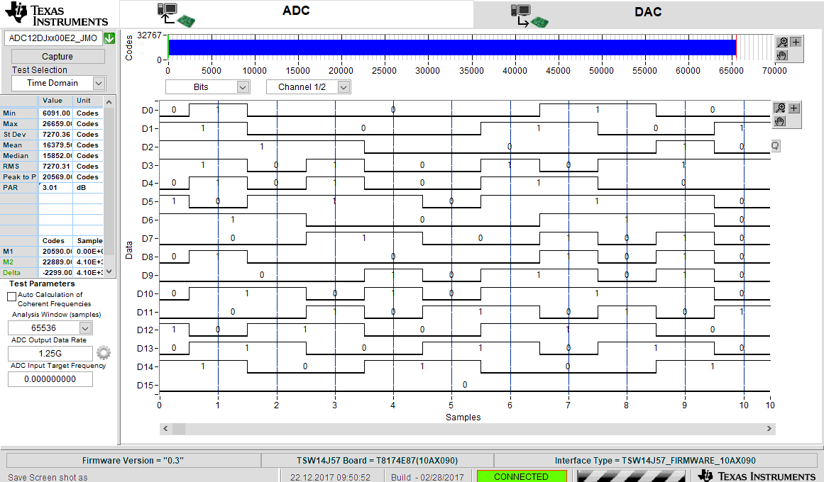
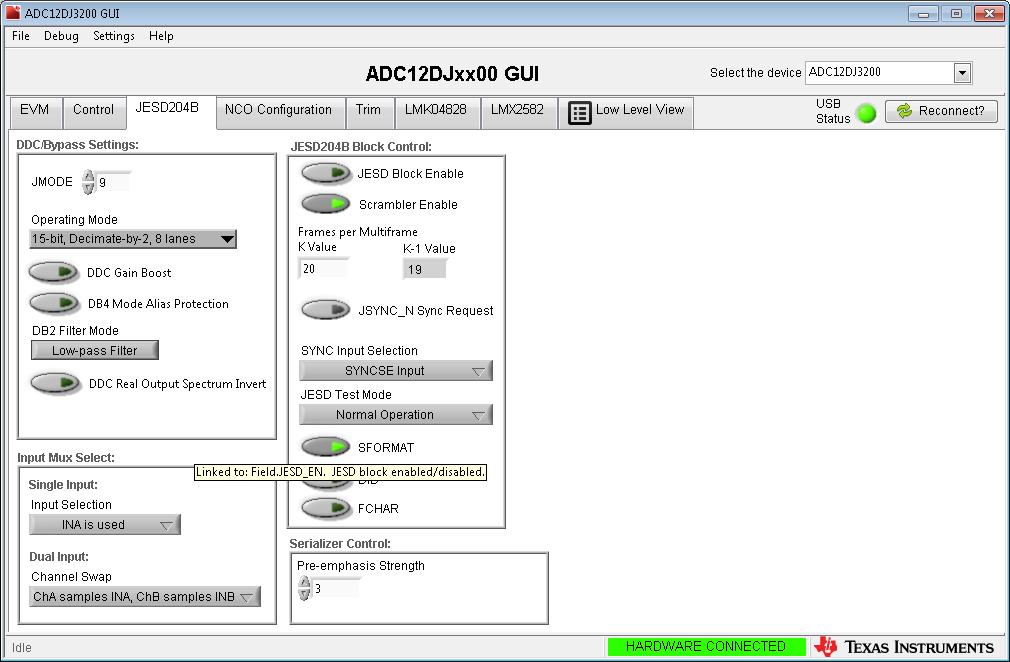
i run the ADC12DJ3200 in JMODE9 and I'm wondering about the output format.

How is it defined in JMODE9?

If I export the raw-data file in HSDC-Pro I get decimal values that are quite bigger than the ADC-resolution (12 bits) allows.

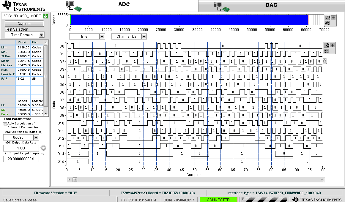
I also don't understand the HSDC-Pro output format in bits. Why are in JMODE9 15 transfered bits and not 12 or even 13, if two's complement is used?

How can I convert the output data in bits into decimal values? Which data format and and how many bits are used in JMODE9?So can you please provide more information about the output format of the ADC12DJ3200 and the HSDC-Pro? In best case for all available JMODE9 settings.

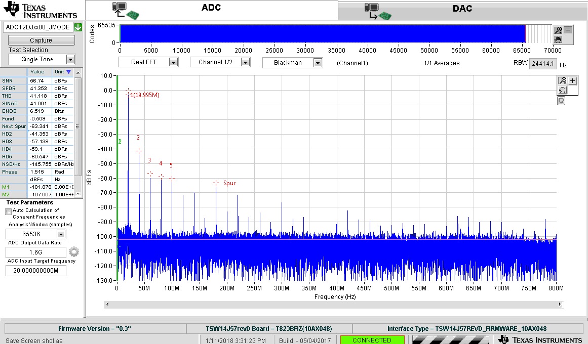
My measurement setup includes the ADC12DJ3200EVM Rev. E3 and the TSW14J57 capture board rev. B. At channel A I applied a sine signal with fin = 300 MHz.

In the attachement, you can find the register settings, and the HSDC-Pro exports.

TI_EVM_JMODE9_withSignal.zip

Thank you very much for your help.

Best regards,

Paul Rott

  • Hi Paul,

    We are taking a closer look at your question, and will be back with you soon.

    Best Regards,

    Dan
  • Hi Paul

    JMODE9 configures the ADC channels as Decimate-by-2 with 15 bit real output data. The ADC itself outputs 16 total bits, with the upper 15 bits containing the ADC information, and the lsb containing the over-range flag information.

    Refer to Table 13 and Table 28 of the ADC12DJ3200 datasheet for details of the JMODE9 data formatting.

    The decimation process does provide some additional resolution beyond the raw 12-bit input, so more than 12 bits are needed. Since the JESD204B data format requires padding up to multiples of 4-bits anyway we made the data format for this mode use a 15-bit format even though the information doesn't really require it. This allowed the same circuitry used on the other decimation modes to be used here.

    The data processing in HSDC Pro for JMODE9 strips off the over-range flag information, and just provides the 15-bit value for Ch1 (DDC A) and Ch2 (DDC B).

    To export the HSDC Pro data I recommend using the menu option File>Save I32 Codes as CSV File. This will provide a file with paired output values for Ch1 and Ch2 in the decimal equivalent of the 15-bit format.

    I hope this is helpful.

    Best regards,

    Jim B

  • Hi Jim,

    thank you very much for your response.

    If I have a look to the sampled values in HSDC-Pro,  I guess that the lower bits contain the information, because the MSB is low at every sample (see attached screenshot).

    Is it possible that HSDC-Pro cuts the LSB with the OVR-information and put the bit on the MSB position?

    Can you please explain, why the decimation process provides more than the 12 bit raw resolution?

    It would be very great to learn more about the additional bits after the decimation.

    What are the values of the additional bits? Are there any bits unused?

    Thank you very much for your help.

    Best regards,

    Paul

  • Hi to everyone,

    after spending more time with the ADC data conversion, I think that I got more information about the conversion from the received bits to the decimal values.

    In every JMODE there are 16 bits transmitted. The datasheet says, bit 0 (LSB) contains the OVR-information. In HSDC-Pro the OVR-information gets cut. The remaining 15 bits are right shifted, so that the LSB of the data is bit 0 and MSB is bit 14. Bit 15 is low the whole time.

    In JMODE9, bit 14 describes the leading sign of the transmitted value:
    1 = positive value
    0 = negative value

    If there is a negative value, the value is calculated via the twos complement. Bit 14 is still reserved for the leading sign.
    If there is a positve transmitted value, bit 0 - 13 are used to calculate the decimal value.

    Am I right? Please feel free to add some comments, if that is not correct!

    Because the ADC is in general a 12 bit ADC, I'm still not sure, why there are 15 bits to represent the digital value?
    Can you please provide some information, why the data word is after the decimation 15 bits long?

    Thank you very much for your support.

    Best regards,
    Paul
  • Hi Paul
    I'm compiling some more data with a Rev A EVM where the .ini file allows all 16 bits to be visible in HSDC Pro. I'll have those results to share with you tomorrow.
    Best regards,
    Jim B
  • Hi Paul

    After looking at the ADC12DJ3200EVM and High Speed Data Converter Pro data in detail I see why the JMODE9 output format has been a little confusing to understand.

    As discussed earlier, in JMODE9 the output data is a total of 16 bits, with the upper 15 bits being the waveform data, and the lsb having Over-range information. As seen from the format definition table EVEN and ODD samples have the Overrange bit set according to either the OVR_T0 and OVR_T1 thresholds.

    The key piece that was not communicated earlier is that the upper 15 bits can be sent as either Offset Binary, or Signed 2's Complement. This setting is controlled by Register 0x204h, Bit 1 (SFORMAT).

    The EVM is configured to use the Offset Binary setting for SFORMAT. So the MSbit is not a sign bit in the data you have been looking at. If SFORMAT is changed to 1, the output data will change to Signed 2's Complement and then the MSbit is the sign bit.

    I gathered some data using the ADC12DJ3200EVM Rev A with the TSW14J57EVM. The data processing for that combination uses all 16 bits so we can see the upper 15 bits of data and the over-range bits.

    Here is a 20 MHz (unfiltered) sinewave sampled at 3200 MSPS with JMODE9. Since this mode decimates by 2 the effective output sample rate of the DDC block is 1600MSPS and the Nyquist zone is therefore DC to 800 MHz (Output Sample Rate/2). The large harmonics seen are typical for a signal generator output that has not been filtered. This is why we normally recommend bandpass or lowpass filters be applied to the input signal for any performance testing.

    Here is the FFT Plot for this setup:

    Here is the Time Domain Codes view for the first 100 samples:

    Here is the corresponding Time Domain Bits view for the first 100 samples:

    In the plot above we can see the bit values go to nearly all 0s for minimim swing and nearly all 1s for maximum swing. The Over-range bits on the lsb are toggling high/low at the peaks because I have OVR_TO threshold set to -0.818dBFS and OVR_T1 threshold set to -0.034dBFS and the input level is at -0.509dBFS. So the peaks are higher than the T0 threshold, but lower than the T1 threshold.

    SFORMAT can be changed from 0 to 1 from the ADC EVM GUI by the following:

    1. Click JESD Block Enable to first disable the JESD204B output block
    2. Click SFORMAT to change this from 0 to 1 (changes to green)
    3. Click JESD Block Enable to re-enable the JESD204B output block

    This is the Codes view with SFORMAT = 1. Since HSDC Pro is expecting offset binary data the result looks odd.

    This is the Bits view with SFORMAT = 1. Now we can see that when bits 14:1 are nearly all 1s the MSbit is 0 since these are the positive values.

    And when bits 14:1 are nearly all 0s the sign bit is 1 for the negative portion of the waveform.

    If you want to look at the data using 16 bit processing you can do so by editing the JMODE9 .ini file. The file you need to edit should be in the following folder location on your PC which uses an earlier pre-production version of the ADC12DJ3200EVM and TSW14J57EVM. 

    C:\Program Files (x86)\Texas Instruments\High Speed Data Converter Pro\14J57 Details\ADC files

    The file is named "ADC12DJxx00E2_JMODE9.ini"

    The key section to edit is shown here:

    Data Postprocessing=0:1
    \\operation:operand
    \\operaion
    \\0=bit shift
    \\1=xor
    \\2=and
    \\3=or
    \\4=not
    \\operand
    \\value(+ve if bitshift by right and -ve if bitshift by left)
    \\E.g 0:-2,1:1024
    \\bitshift by left 2 times and then xor by 1024
    Number of Bits=15

    The updated version should look like this:

    \\Data Postprocessing=0:1 - Comment this out to remove the 1 bit shift to the right
    \\operation:operand
    \\operaion
    \\0=bit shift
    \\1=xor
    \\2=and
    \\3=or
    \\4=not
    \\operand
    \\value(+ve if bitshift by right and -ve if bitshift by left)
    \\E.g 0:-2,1:1024
    \\bitshift by left 2 times and then xor by 1024
    Number of Bits=16   \\ Change this to 16 bits

    You had also asked about how we get more bits of resolution starting from the 12 bit data from the ADC. In general over-sampling and then using decimation filtering can provide effectively higher SNR and resolution.  Decimating by only a factor of 2 does not provide much increase in SNR, and wouldn't necessitate 15 bits of resolution, however since we already have filters and output formats with this data width to support the higher decimation factors available in the ADC12DJ3200 we used the same resolution for JMODE9.

    Here is a link to one discussion on this topic:

    https://e2e.ti.com/blogs_/b/analogwire/archive/2015/08/21/rf-sampling-how-over-sampling-is-cheating-physics

    I hope this helps.

    Best regards,

    Jim B

  • Hi Jim,

    thank you very much for your very detailed response. That helped a lot!

    If I change the .ini file to receive 16 bit, I can see the OVR bit in HSDC-Pro.
    I suppose, the calculation of the decimal values in HSDC-Pro, does not respect the reserved bit for the OVR information and include this bit in it's conversion to decimal values. So the exported decimal values in the .csv file should be used very carefully.
    Can you confirm this?

    Thank you very much!

    Best regards,
    Paul