This thread has been locked.

If you have a related question, please click the "Ask a related question" button in the top right corner. The newly created question will be automatically linked to this question.

ADS1292R: difficulties on supply ADS1292R component

Part Number: ADS1292R
Hello fellows I have buyed a QFN-32 breakout PCB, and i soldered the component ADS1292R, now I am with dificults in powered him. Based on the datasheet I checked that the component needs to be powered with analog and digital voltage. I intend to develop a project that is single supply, how can I get digital power for the pin 23 (DVDD) and pin 24 (DGND) of the component ADS1292R
  • Hello Armando,

    Thanks for your post!

    Do you know what voltage levels you would like to use?
    What are your initial supply options?
    What is the voltage level that your uC will be using to avoid level translation for digital communication?

    For example, you could use a 5V bus, LDO to 3V for AVDD, and an additional LDO to 1.8V for DVDD.

    As mentioned in the "Power Supplies and Grounding" section of the datasheet, it is important to make sure that your analog and digital return currents are separated.
  • Hello Alexander , 

    Thank you for answering my question.

    my project will have voltages around a 3.7V battery, although I regulate the voltage to the battery output to 3.3V, this will be the voltage with which the entire project will work.

    My source is a USB, which inserts into the 5V USB port, after that I have a charge regulator that regulates an output of 4.25V, to the battery charger. After this I had already planned to put a regulator "TPS73033DBVR" to lower the voltage to 3.3V (at this stage I get the voltage needed to power the ADS1292R analogic AVDD).

    I have another regulator "TPS73033DBVR", but it has a standard fixed voltage of 3.3V, so it would need a voltage of 1.8V, maybe through a voltage divider you can get the 1.8V needed, however I do not know to what extent the digital current obtained through this form will be stable.

    Because I wanted to separate the analogue current from digital, this was the reason why I asked how this could be done

  • Hi Armando,

    Happy to help!

    You are correct on all accounts. I worry about using a resistor divider to generate 1.8V as well since it will generate thermal noise. To confirm best practice, I would recommend creating a post on the regulator forum.

    e2e.ti.com/.../321

    Using a 3.3V to 1.8V LDO could work as well. This should help isolate the analog and digital currents.
  • pricey Alexander,
    Thanks for your help and readiness in responding, certainly other issues will emerge and it would be a great  to count with your help on their availability .

  • Alexander,

    I have another doubt, the Analog ground (AVSS) and the digital ground (DVSS) should share a common point. 

    After doing the first voltage regulate I get a 3.3V output that will be the AVDD, from the same point where I share the voltage regulator for the 3.3V is where I go to get the voltage to regulate for DVDD, now the doubt appears in GROUND's

    Note:(I will update the post with the power scheme for the ADSR1292R)

  • Hi Armando,

    It is common practice to tie these grounds together using a 0Ohm resistor. It is important to make sure that the ground connections that are on the component side of the board have a direct path and do not conflict with other signal traces.
  • Alexander, there is some way to get the digital ground without the use of this resistance, the idea was to test and program the component with the help of the microcontroller. In my city I can not get this value of resistance, so I have to wait a few days, this stops
    development
  • Armando,

    Tying the grounds together without a 0Ohm resistor should be fine if the connection is placed strategically such that the return paths do not interfere with other signal traces.
  • Hi Alexander ,
    I still  have problems with supply . I have done a lot of measures with a multimeter, and without connect the microcontroller pins(DRDY,DOUT,CLK,DIN,CS,CLK,...) all things are great and apparentlly ok., In  the "DVDD" I get 1.8V  and in the "AVDD" 3.3V. The problem begin when I connect the rest of the pins  of microcontroller the voltage drop to 0.60V in the VDD pin and 2.42 approximately on the VDD pin. it's this normal? I have to program the uC, but Until I get it the right  supply I can not do it.

  • Hi Armando,

    No this is not normal. It sounds like your supplies are current limiting, they are not capable of supplying the current being demanded by the system. This causes a voltage drop.

    Can you post a schematic?
  • Hello,

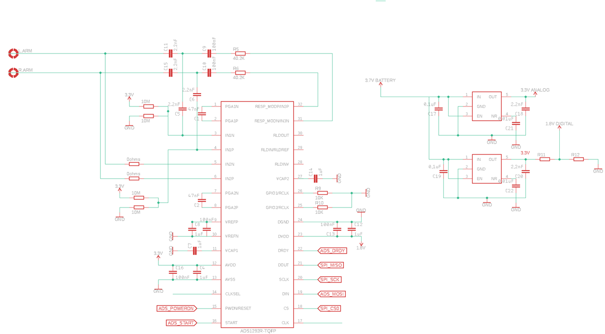
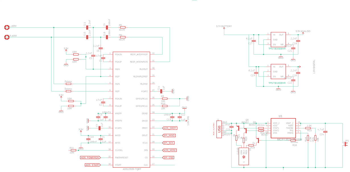
    This is the schema who i'am building. So it has been update constantly

  • Hi Armando,

    Thanks! Can you post the rest of the schematic that shows where your 3.3V & 1.8V net comes from?

    What are you using to supply the power?
  • is powered by a 5v USB, after that the voltage is regulated by two voltage regulators. first to 3.3V where the analog voltage is obtained. Second regulated to 1.8V where the digital supply is obtained. I'm finished designing the scheme on eagle I'll update the post
  • Armando,

    Looking forward to it! I would take a look at your power chain and make sure that all of the components (USB, LDOs) are capable of supplying the current that the load is drawing.
  • Alexander I have update the scheme and already have done that verification and all seems to be ok, this part of the sistem is supplied by USB charger, and the uC is supplied through a pc USB port because is a Launchpad

  • Hello Alexander, 

    Is it possible that the board is corrupted? What can I do to verify the problem

  • Hi Armando,

    It is possible, I am not sure what kind of ESD precautions you are taking.

    You can probe the VCAP pins to check to make sure, but I don't have any reason to believe that the device has been damaged. Can you verify your power up sequence is as recommended in the datasheet and probe your supplies to ensure that they are clean without noise?

    VCAP1: AVSS + 1.2V
    VCAP2: (AVDD+AVSS)/2
    VCAP3: AVDD + 1.9V

    Your schematic says 3.7V battery, not 5V USB.

    Please provide the part number of the regulators being used and confirm the current that they are capable of supplying. The USB charger as well. Then cross that against the current drawn by the device, your uC, and everything else that is drawing current to make sure that you are not current limiting the regulators.

    From what you told me in your previous post, this is most likely the problem. Since everything looks fine until you introduce the additional load of the uC, it makes me think that the extra load is more than the regulators are capable of driving.
  • I have a micro usb 5V supply, and a power management charger regulator, to regulate the battery charge. After that is the attached circuit, two regulators each one with distinct output voltage. My doubt are the grounds, the analog is correct , but the problem is in the digital. I am Using two regulator Texas Instruments TPS73033. I already seen that questions, and I am think my digital ground circuit is not well isolated, a the charge is looping. Can you help me to redefine my schema
  • Using a resistor divider to create the 1.8V digital voltage from a 3.3V regulator is not ideal because of thermal noise. Is it possible for your to use a 1.8V otuput regulator? What is the value of R11 & R12?

    If you post your layout I can take a look at your grounds.
  •  Hello Alexander,
    I send you my Schematics. I already change the resistor divider for a 1.8V output regulator.
    So in the schema i show how the circuit is actually mounted, to verify the problem of drop voltage when i connect the SPI pins, I have supplied the circuit with two power sources.
    -1rst source connected to the usb, is supplied from a 5v charger, this supply all the charger management battery, voltage regulator's and ads1292R.
    -the second source only supply the microcontroller with USB pc port.
    So I can't understand what i' am doing wrong a need test my code but with this drop voltage is not enough, to do the test's because it does not meet the minimum the analog and digital voltages

  • Hi Armando,

    To confirm, you are still seeing the voltage drop after connecting the uC with the second power source?

    Where is the rest of your schematic showing the uC?

    Note: It looks like your 100nF cap on VREFN is not connected. Might just be a visual bug though.
  • Yes , all that components represented in the schema are sourced by a charger with 5V , the ucC is power sourced by the 5V PC USB port. This voltage drop is present  then I conect the pins , MISO, MOSI CS, CLK, START,...
    Iam using a arduino to made some tests, but the final uC is to integrate with launchpad MSP432, this is why I don't show the rest of the schema

  • Hi Armando,

    The digital pins connection is most likely being made incorrectly, leading to a short.
  • Hello Alexander
    I do not understand, there should be some pull-up resistor between this IC and the uC?because there is no error in the connections, I checked them several times.

    regards

  • Hi Armando,

    Some customers choose to use a pull-up resistor for pins that they would like to keep high such as /CS. It's not necessary though.

    The symptoms of the issue sound like there is a low resistance path to ground being created when you connect the digital pins. This is causing the current limit on the supply of the device to be stressed and therefor the voltage drops to limit the current and protect the device.
  • Hi Alexander,

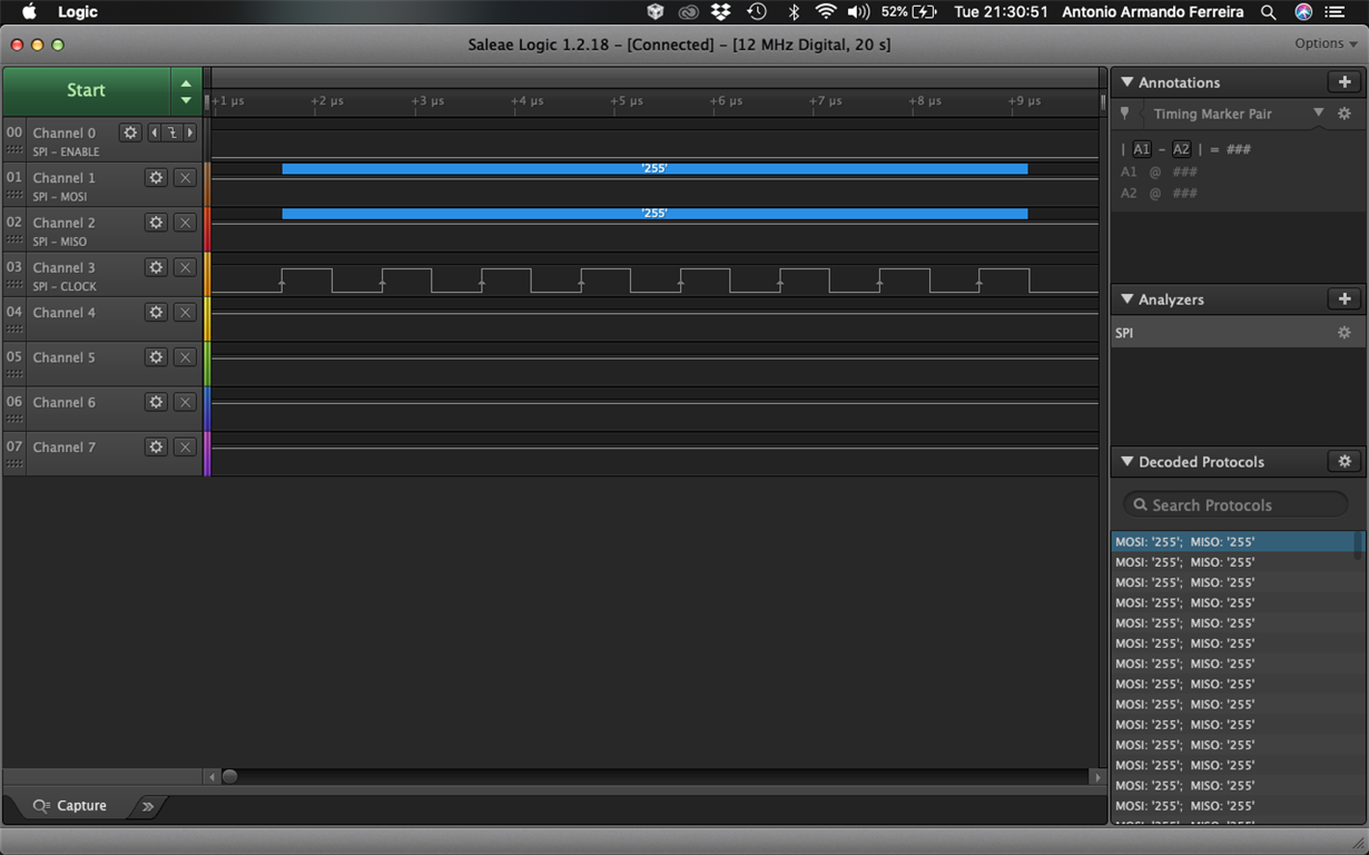
    I used a logic analyser to verify the SPI communication, with ADS1292R and I get some curious results.

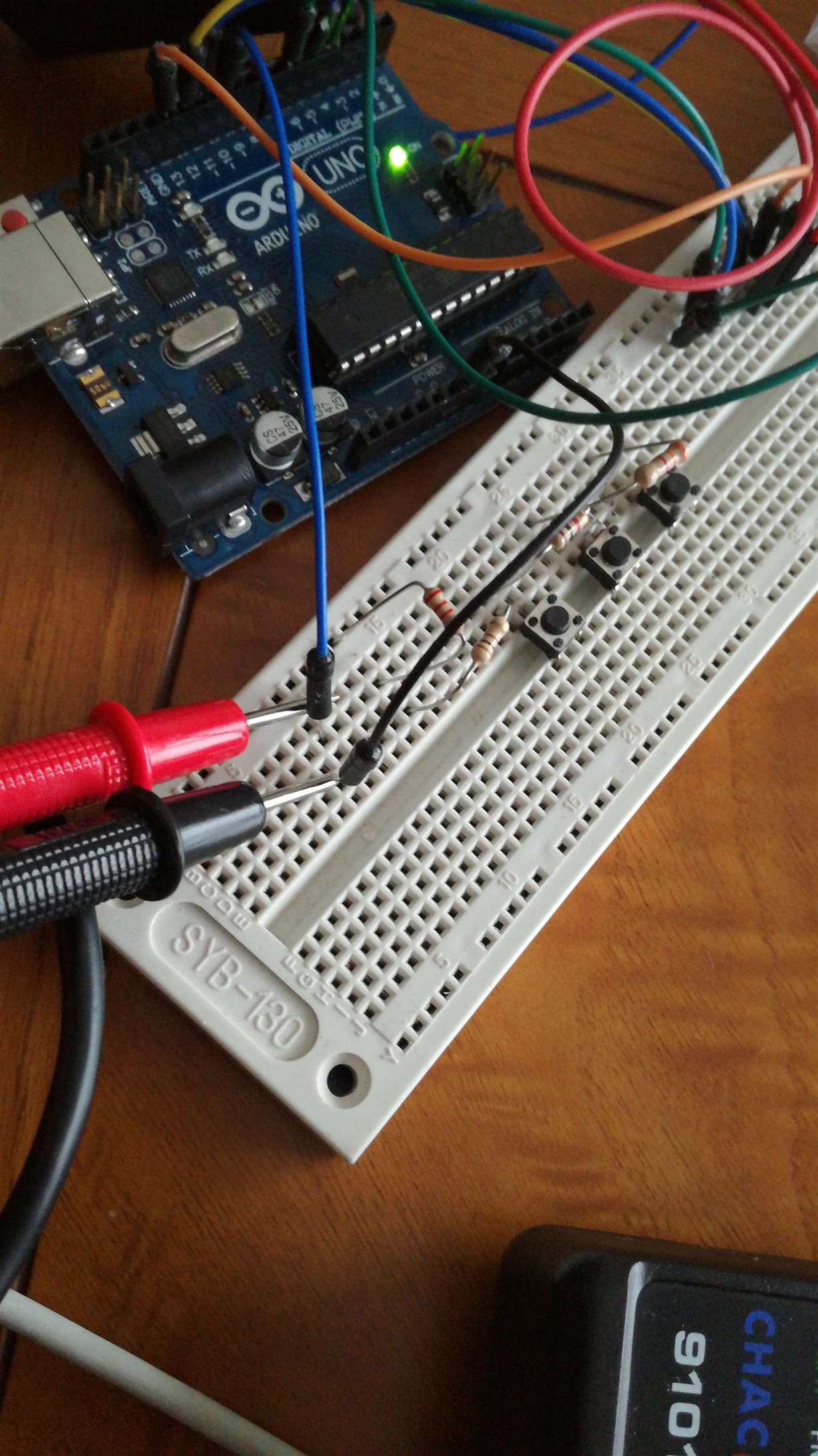
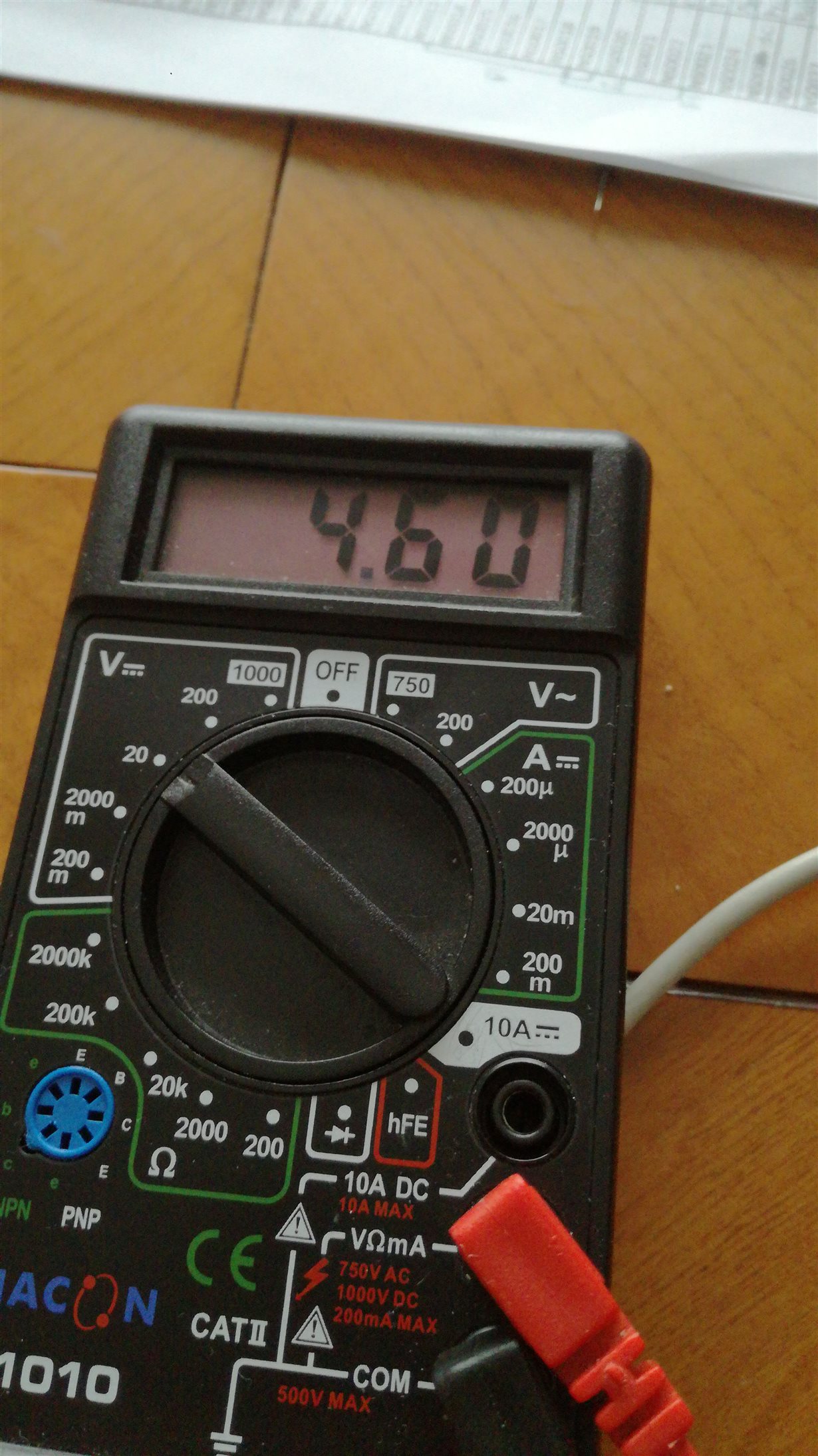
    After this,  I decide measure with a multimeter  the CS pin of the SPI communication, and I verify  4.60V, it's to high, I think. for this reason I ask if the SPI communication between the microcontroller and the ADS1292R should not take some pull-up resistors

  • Hi Armando,

    The digital pins voltage magnitude should be equal to the digital supply of the device. You may need level translators or pullup/pulldown resistors if the digital logic is operating at a different magnitude for the arduino.
  • Alexander Smith, the problem is solved tank you
  • Wonderful to hear Armando!

    You are most welcome! Please let us know if you have additional questions!