This thread has been locked.

If you have a related question, please click the "Ask a related question" button in the top right corner. The newly created question will be automatically linked to this question.

ADS1298: ADS1298 SPI

Part Number: ADS1298

Hello ,I am unable  to get the data from ADS 1298 with Arduino using SPI protocol.

Please help me..

Below I Attached H/W and S/W configuration for this..

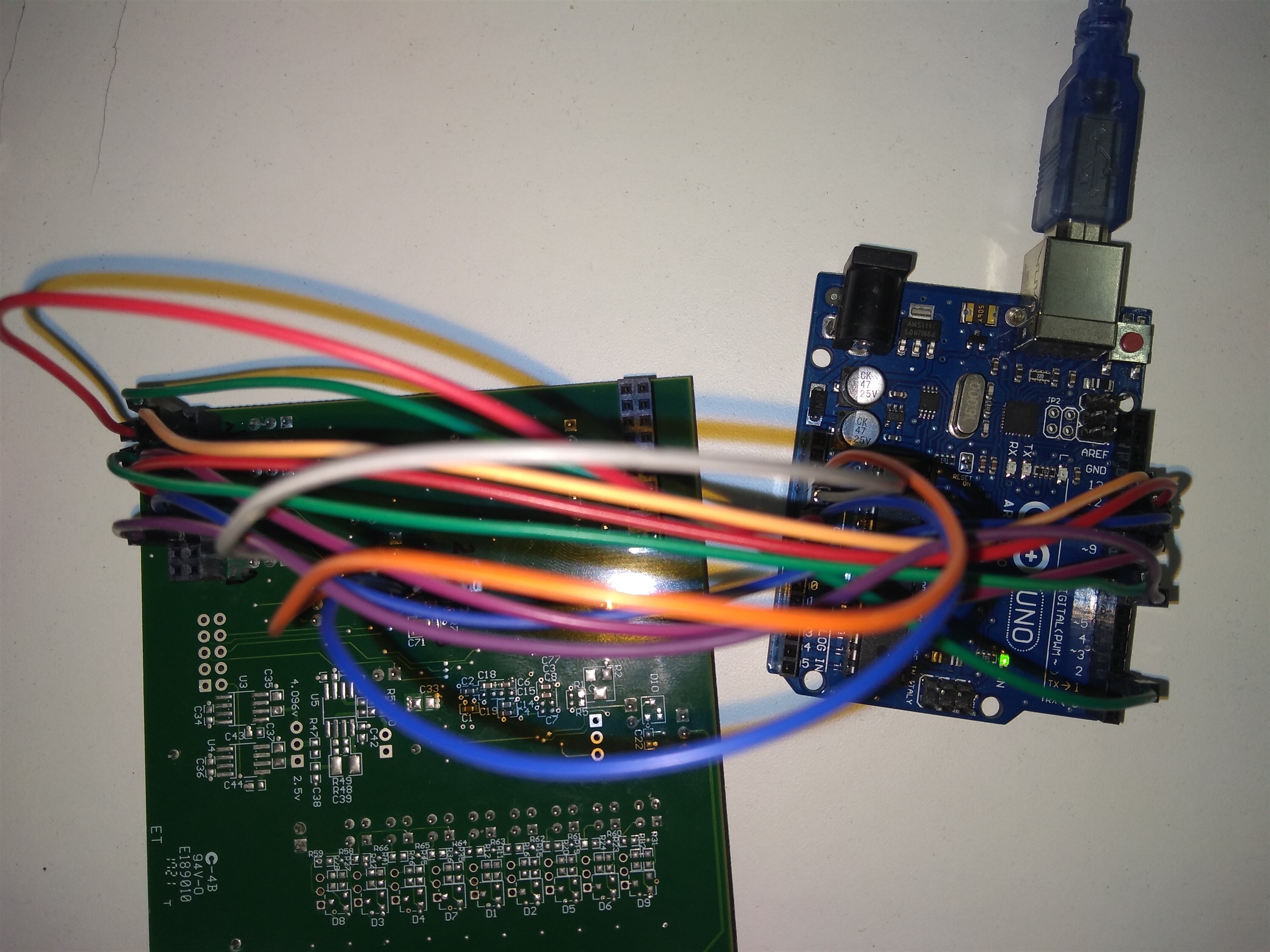
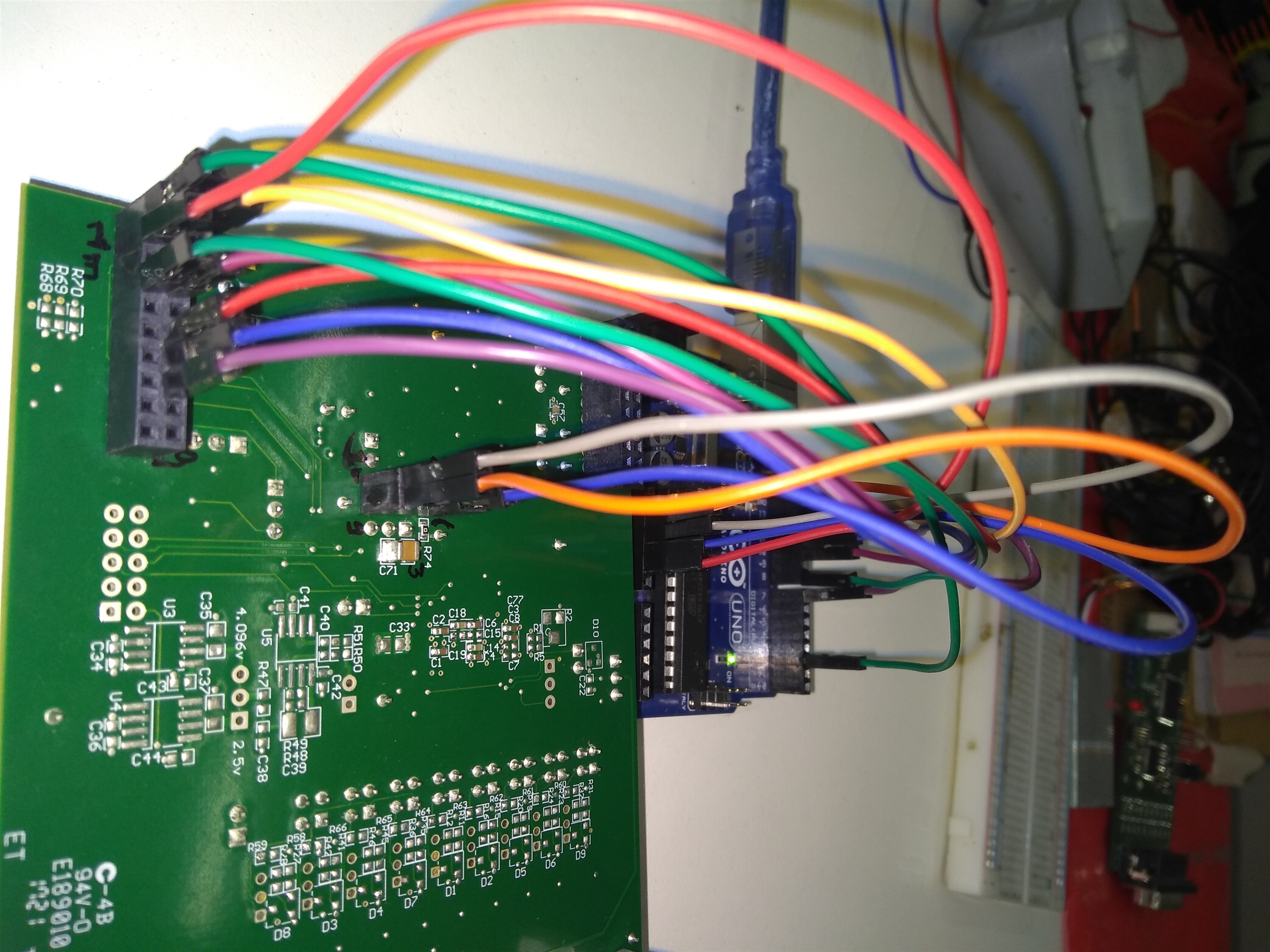
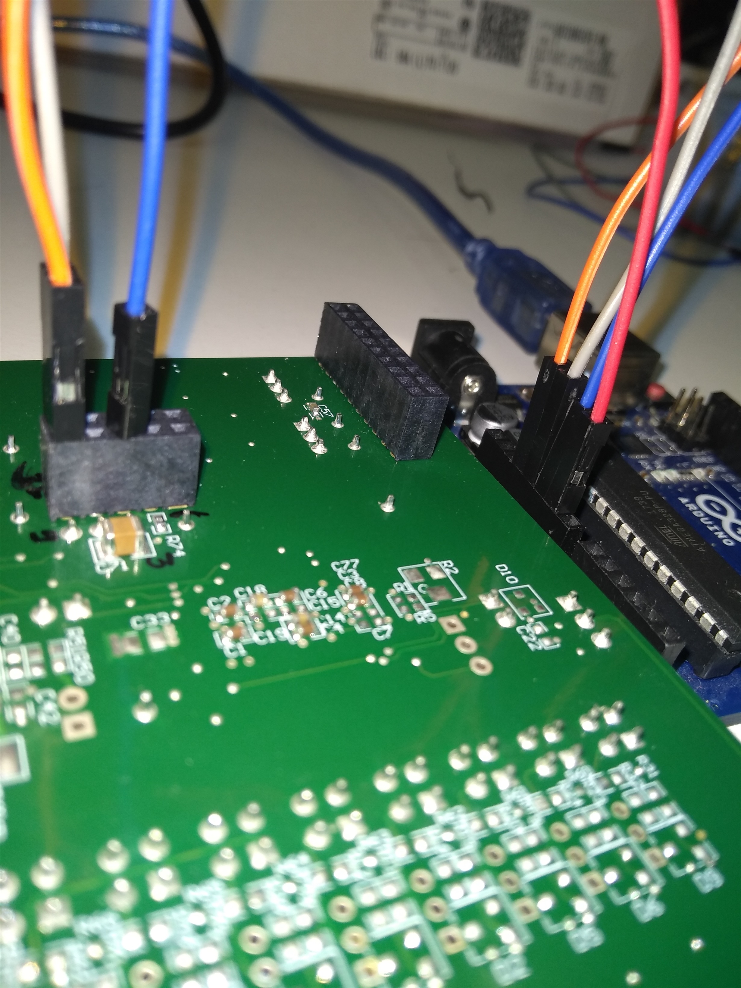
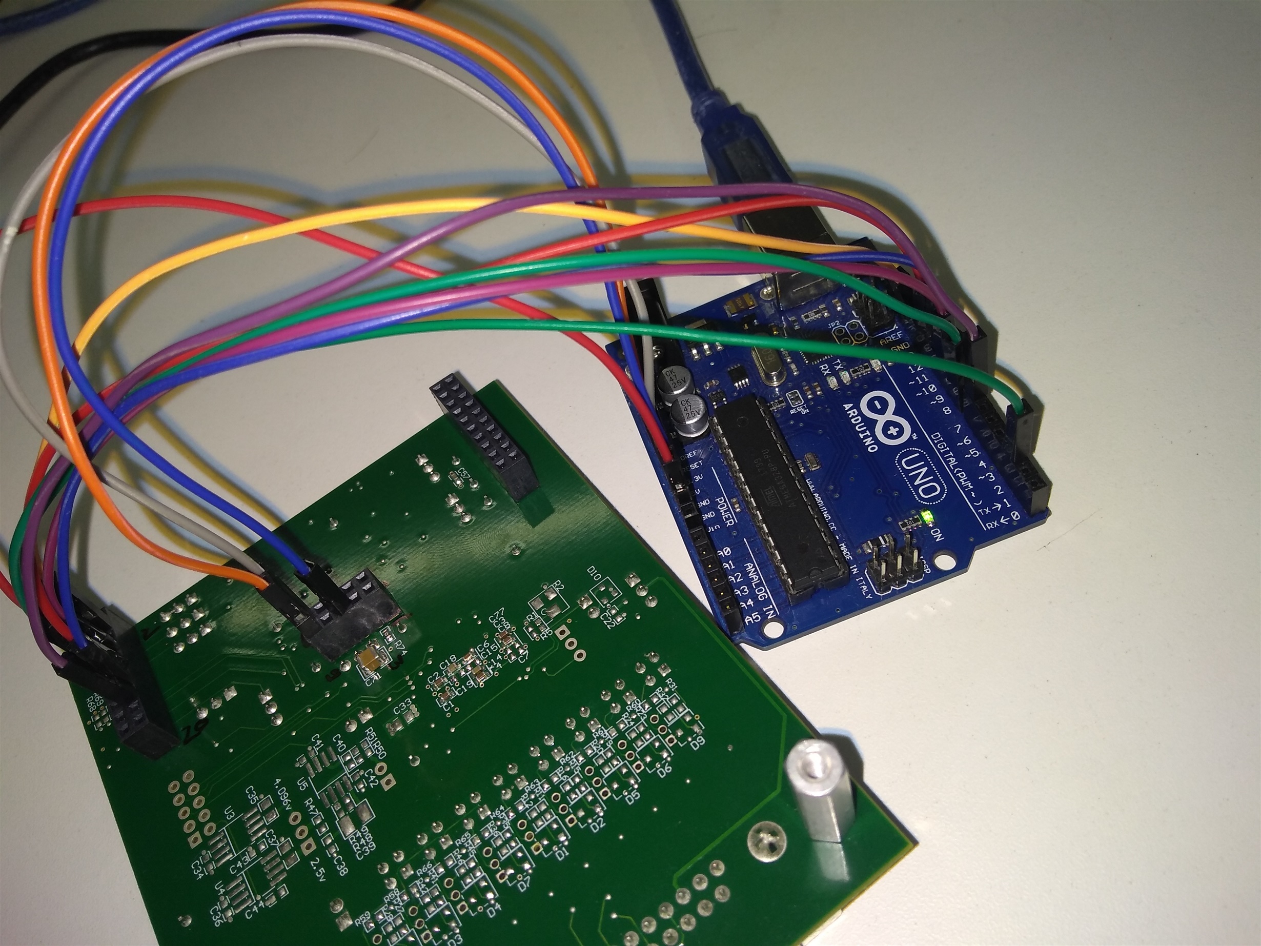
ARDUINO CONNECTION WITH ADS 1298 ECGFE BOARD


J3.3 SCLK connected to Arduino pin 13

J3.4 GND connected to Arduino pin GND common.

J3.7 CS complement connected to Arduino pin 10

J3.8 RESET connect to Arduino pin 7 .

J3.11 DIN connected to Arduino pin 11 

J3.13 DOUT connected to Arduino pin 12 

J3.15 DRDY connected to Arduino pin 3 (programmed)

J4.9 power supply is 3.3V

J4.5 connect to Arduino GND

Software code for ADS 1298 with Arduino UNO.

#include "ads1298.h"
#include "adsCMD.h"
#include <SPI.h>
  
int gMaxChan = 8;
//int gIDval = 0; 
//int activeSerialPort = 0;
//const int kPIN_LED = 13;

void setup(){
  using namespace ADS1298;

  pinMode(IPIN_CS, OUTPUT);
  pinMode(PIN_START, OUTPUT);
  pinMode(IPIN_DRDY, INPUT);
  pinMode(IPIN_RESET, OUTPUT);
   
  SPI.beginTransaction(SPISettings(16000000, MSBFIRST, SPI_MODE1));
  SPI.begin();
  //SPI.setBitOrder(MSBFIRST);
  SPI.setClockDivider(SPI_CLOCK_DIV4);
  //SPI.setDataMode(SPI_MODE1);
  delay(100);

  adc_send_command(SDATAC);
  delay(10);
  Serial.begin(9600);
  adc_rreg(0x20);
  while (Serial.read() >= 0) {} 
  delay(200); 
}

void loop()
{
  long buffer[50];
  int incomingByte = 0;
  static unsigned long tLast = 0;
   
  if (Serial.available() > 0) 
  {
    incomingByte = Serial.read();
  }
  
  if(millis()-tLast < 500)
  {
    tLast = millis();
  }         
    unsigned long tStart = millis();
    for(int channel = 1; channel <= 8; channel++)
    {
      byte value[10];
      value[0] = (byte) (buffer[channel]>>8);
      //value[1] = (byte) (buffer[channel]>>16);
      //value[2] = (byte) (buffer[channel]>>8);
      //value[3] = (byte) (buffer[channel]);

      Serial.println(value[0]);
      //Serial.println(value[1]);
      //Serial.println(value[2]);
      //Serial.println(value[3]);
    }
}
  • Hello Sagar,

    Thanks for your post and welcome to the forum!

    Your pin connections look fine so this is probably a software problem. Can you confirm that you're following section 10.1.1 Setting the Device for Basic Data Capture in the datasheet?

    e2e.ti.com/.../705896
  • Hello sir.

    Thanks for your reply.

    I am able to get the ID value as 0(below i attached my sample code for this).

    So ADS 1298 is communicating with Arduino .But issue is that i can not get specific channel data on serial monitor.also i have checked your suggested section and forum for basic data capture process of ADS 1298 and apply all configuration in software.But still not get Channel data.

    Also i have another question is that is all 8 channel active is same time.if yes then Arduino UNO board is capable of receiving all channel data simultaneously?

    Can anyone please answer my questions...

    #include "ads1298.h"
    #include "adsCMD.h"
    #include <SPI.h>
      
    void setup(){
      using namespace ADS1298;
    
      pinMode(IPIN_CS, OUTPUT);
      pinMode(PIN_START, OUTPUT);
      pinMode(IPIN_DRDY, INPUT);
      pinMode(IPIN_RESET, OUTPUT);
     
      SPI.begin();
      SPI.setBitOrder(MSBFIRST);
      SPI.setClockDivider(SPI_CLOCK_DIV4);
      SPI.setDataMode(SPI_MODE1);
      Serial.begin(115200);
      adc_send_command(SDATAC);
      delay(500);
    }
    
    void loop()
    {
      int ID;
      digitalWrite(IPIN_CS, LOW);
      SPI.transfer(0x20);
      delayMicroseconds(10);
      SPI.transfer(ID);
      delayMicroseconds(10);
      digitalWrite(IPIN_CS, HIGH);
      Serial.println(ID);
      delay(100);
    }

    it may be helpful in my project.

  • Hi Sagar,

    Happy to help!

    You should not receive a value of 0 for the ID. You should receive 010 for the ADS1298 as per section 9.6.1.1 of the datasheet.

    If this is the case then I think there is an issue in your setup or early communication steps. I would focus on receiving the ID correctly before
    capturing data. Ryan covers the startup process nicely in the first post below:

    e2e.ti.com/.../658195
    e2e.ti.com/.../631106

    Probe your supplies to make sure that they are operating as expected. Issuing the extra /RESET may fix the issue as well.
  • Thanks for your reply.
    Is there need to supply 5V to ads 1298 along with 3.3 V ? because in data sheet maximum i/p voltage for ads 1298 is
    3. 6 V (DVDD )as mentioned..
  • Please reply me..
    This may be help in my project.I really need your help..
  • Hi Sagar,

    Sorry for the delay in my response, I was out of the office.

    There are two power supplies, AVDD and DVDD. You can use a bipolar or uni polar configuration. Please refer to section 11 of the datasheet, Power Supply Recommendations and 7.3 Recommended Operating Conditions.
  • Thanks for your reply sir

    I follow the procedure of connecting power supply as per datasheet .
    applied on

    j4.5 - GND - Arduino GND
    J4.9 - 3.3V - Arduino 3.3V
    J4.10 - 5V - Arduino 5V

    also i have doubt on J27 jumper setting as discussed in forum.it is need.It is really needed?

    Answer by Tom Hendrick(e2e.ti.com/.../168648)

    CLKSEL is controlled by JP27. If you have the shunt on pins 1-2, CLKSEL = 0 and you need to use an external modulator clock. This is provided by (defaults to) the 2.048MHZ clock on the eval board. If you open JP27 (completely remove the jumper) the CLKSEL pin is pulled high and the ADS1298 would run from its internal oscillator.

    When i see SPI configuration on logic analyzer software there has been variation in SCLK pulse. This is bit confusing me.

    Is there any other way to check that ADS 1298 is transmitting data to arduino on logic analyzer software?
    I have confusion in h/w connection.

    so please reply me.
  • Hi Sagar,

    I'm not able to open that forum link.
    I do not see JP27 as controlling the clock, do you mean JP23?

    You want your clock sources to by synchronized so that the data is processed correctly. This means that your Arduino and the device should be sharing the same external clock source.

    SCLK, is not CLK. SCLK is what is sent to the device to clock the data out whereas the CLK is what controls the timing for the device.

    Try putting GND on AVSS, JP20.2
    5V on AVDD, JP2.2
    3.3V on DVDD, JP19.1
  • Hello,sorry for delay from my side

    I want to use internal clock of ads 1298 so i set JP24 (2-3)as per user guide of ADS1298 ecgfe-pdk .Is it ok?

    and as per your suggestion i connected supply to

    GND on AVSS-JP20.2

    5V on AVDD-JP2.2

    3.3V on DVDD-JP19.1

    but when i measure power  supply on given test point then it give 3.3 V correctly but when i measure 5V  it shows me zero.

    Then I modified power supply connection as like

    J4.5 - GND

    j4.9 - 3.3 V

    J4.10 - 5 V

    and when i test power supply on given test point it gives me 3.3 V and 5.0 V correctly.So power supply issue is solved i think?

    is ADS 1298 is capable of transmitting data @  rate of 1 MHz(SPI_CLOCK_DIV16);) as i stetted in code?

    It seems look that hardware connection is correct as per my concerns So there is a problem in a code. Here i upload my code.after long time i can not find correction in my code.Can you please tell me correction in my code (for capture basic id of ads 1298 and print on to serial  monitor of arduino).

    #include "ads1298.h"
    #include "adsCMD.h"
    #include <SPI.h>

    int gMaxChan = 8;
    int gIDval = 0;
    int activeSerialPort = 0;


    void setup()
    {
    using namespace ADS1298;

    pinMode(IPIN_CS, OUTPUT);
    pinMode(PIN_START, OUTPUT);
    pinMode(IPIN_DRDY, INPUT);
    pinMode(IPIN_RESET, OUTPUT);

    digitalWrite(PIN_START,LOW);
    digitalWrite(IPIN_CS, HIGH);
    delay(500);

    SPI.begin();
    SPI.setBitOrder(MSBFIRST);
    SPI.setClockDivider(SPI_CLOCK_DIV16);
    SPI.setDataMode(SPI_MODE1);
    Serial.begin(115200);
    while (Serial.read() >= 0) {}
    uint8_t gMaxChan = adcSetup();
    if (gMaxChan == 0) {
    while(1) {
    Serial.println("ADC Error");
    delay(1000);
    }
    }

    Serial.print("ADC detected has ");
    Serial.print(gMaxChan);
    Serial.print(" channels\n");
    gMaxChan = adcSetup();

    if (gMaxChan == 0) {
    while(1) {
    Serial.println("ADC Error");
    delay(1000);
    }
    }
    Serial.print("ADC detected has ");
    Serial.print(gMaxChan);
    Serial.print(" channels\n");
    }

    int8_t adcSetup()
    {
    using namespace ADS1298;

    digitalWrite(IPIN_RESET, HIGH);
    delay(1000);
    digitalWrite(IPIN_RESET, LOW);
    delayMicroseconds(1);
    digitalWrite(IPIN_RESET, HIGH);
    delayMicroseconds(9);
    adc_send_command(SDATAC);
    delayMicroseconds(5);

    adc_wreg(CONFIG3, RLDREF_INT | PD_RLD | PD_REFBUF | CONFIG3_const);
    adc_wreg(RLD_SENSP, 0x01);
    adc_wreg(RLD_SENSN, 0x01);
    adc_wreg(GPIO, 0x00);

    adc_wreg(CONFIG1, HIGH_RES_1k_SPS);
    adc_wreg(CONFIG2, INT_TEST);
    adc_wreg(CH1SET, ELECTRODE_INPUT | GAIN_12X);
    for (int i = 2; i <= 4; i++) {
    adc_wreg(CHnSET + i, PDn | SHORTED);
    }
    int IDval = adc_rreg(ID) ;
    }

    void loop()
    {
    Serial.print("Device Type (ID Control Register): ");
    Serial.print(gIDval);
    Serial.print(" Channels: ");
    Serial.println(gMaxChan);
    }

    Please help me ...

  • Hello Sagar,

    As per the document I am referencing: JP24 controls the digital supply voltage, DVDD, not internal or external clock selection. JP24 2-3 sets DVDD to 1.8V, if you are using 3.3V to communicate with the Arduino it may not work as expected. I recommend matching digital logic voltage levels.

    www.ti.com/.../sbau171d.pdf

    Sorry for the confusion, I wonder if we have been looking at different documents. Confirm that the correct voltages are making it to the power pins of the device to be certain.

    1MHz is fine for SCLK.

    There are a couple of things to confirm with your code:

    Make sure you're issuing the reset command after power up sequencing as indicated in section 11.1 of the datasheet.
    Follow the steps in section 10.1.1 Setting the Device for Basic Data Capture.

    Are you able to see DRDY pulse?
  • Hello sir

    I am using same User guide as provided by TI for ADS1298 ECGPCK-FE .

    and how i see DRDY pulse on oscilloscope. Can you suggest me connection.As per my point of view slave device is oprated by Internal Oscillator as i jumper setting to OSC1 JP19 1-2: OSC1 enabled and use JP23 CLKSEL source 1-2: External Master Clock.as my MASTER device is arduino that provide Clock to ADS 1298 for SPI Comm.

    is that ok?
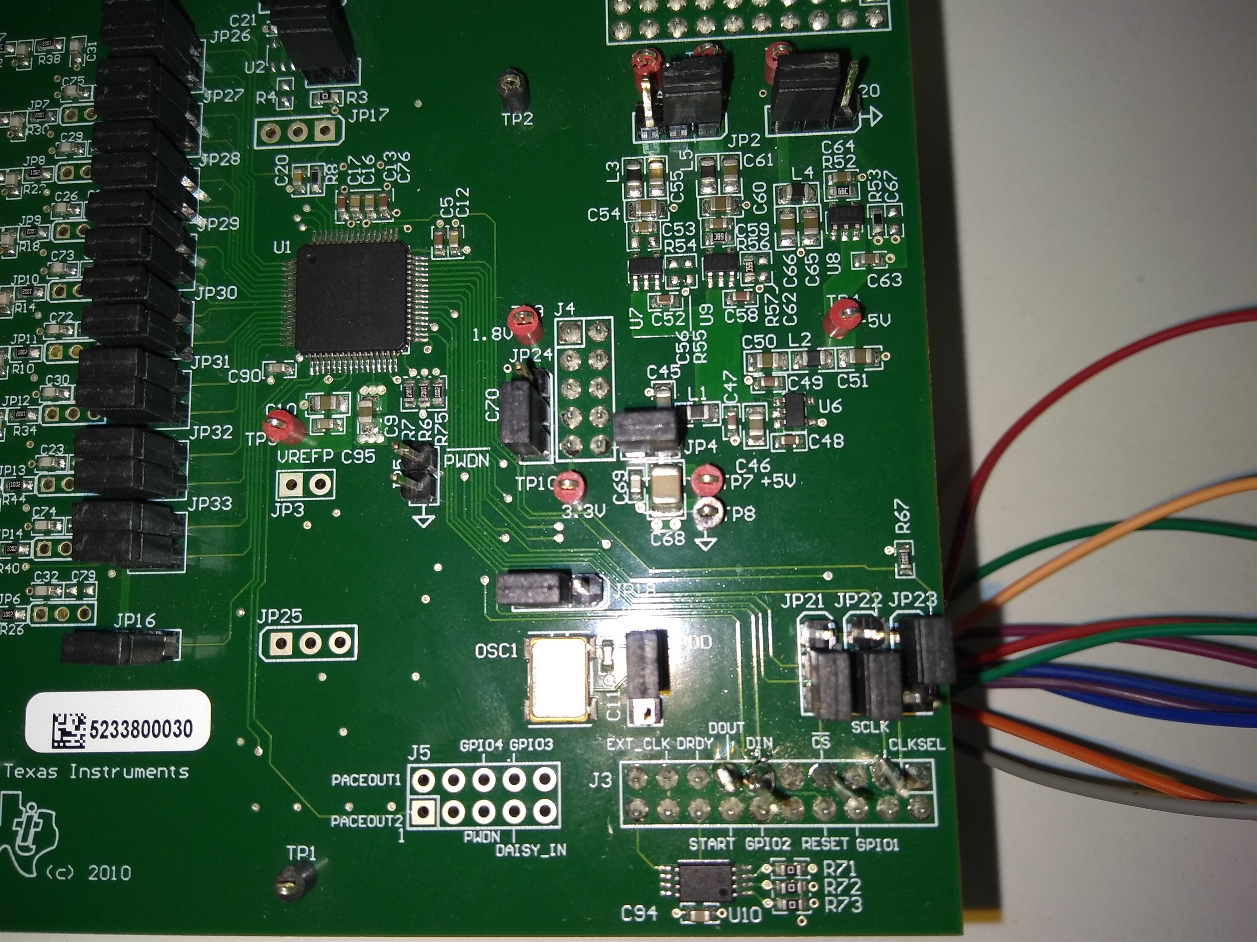
  • Here i upload my h/w connection picture please look this and tell me is this is correct wiring and jumper setting is ok?

  • Hi Sagar,

    Pin 47 is /DRDY. Just connect an oscilloscope and look for the pulse. You may need to solder in a fly wire on the J3 header.

    The slave device should not have the internal oscillator enabled, it should be using the same clock as the master.

    It's kind of difficult for me to understand the connections since they're made on the bottom of the board. The default jumper locations are in the user's guide and I recommend reviewing the connections there.
  • Hello sir ,

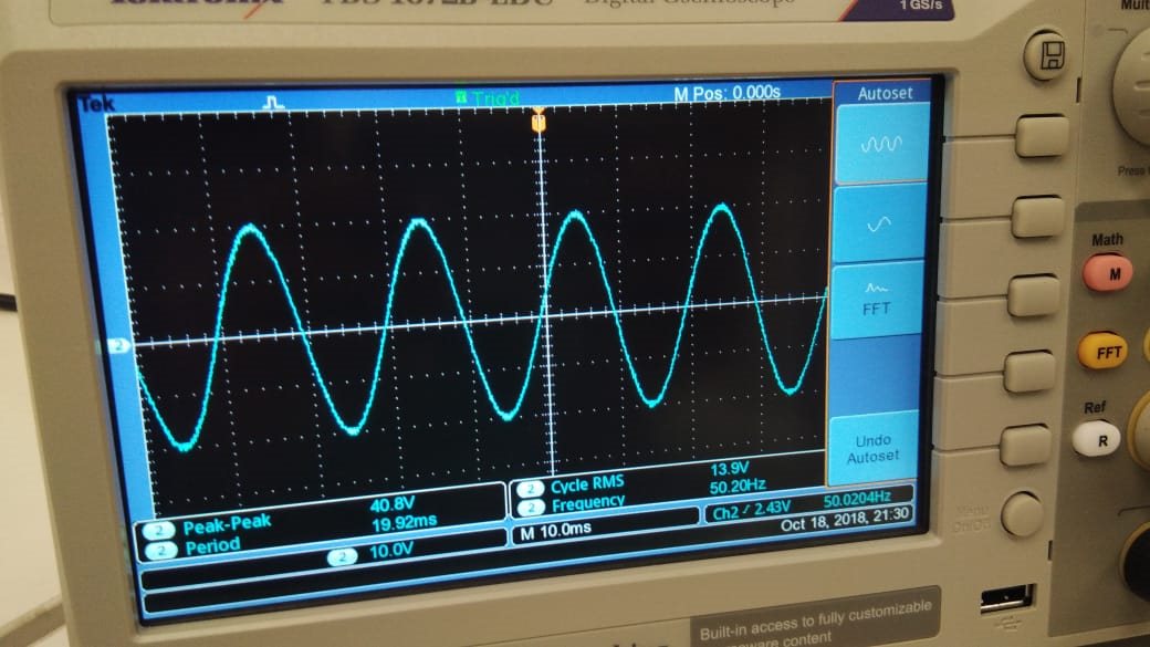
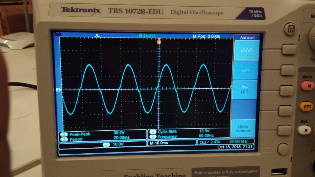
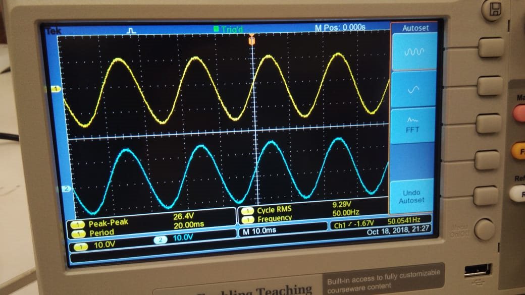
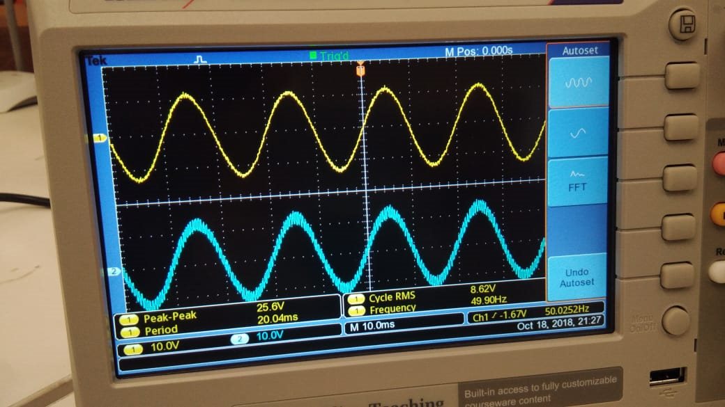
    YES I am able to see DRDY signal on oscilloscope it is confirm that ADS1298 IC is working correctly. Below i attached picture of my DRDY,DIN,DOUT and CLK signal results which is taken from oscilloscope  display.

    So can you verify that there is no h/w issue.So i will work on s/w  side.

    1>DRDY Sgnal on Oscilloscope - PIN no.  - 47 of ADS 1298

    2> DIN signal - PIN no. - 34

    3> DOUT Signal with ref. to GND(yellow line is ground line.) - PIN 43 of ADS 1298

    4> CLK signal of ADS 1298 with reg. to GND (Pin 37) 

    Please help me..

  • Hi Sagar,

    Are you using a sine wave as a clock signal? Clock signal should be a square wave.

    DRDY should be a pulse, not a sine wave. Take a look at the DRDY pulse from this thread to see what I mean: e2e.ti.com/.../666463

    Why do you have a sine wave on your ground?

    I think your probes are set to 10x as well.
  • Hello sir

    When i connects ADS 1298 board with Host MMB0 board and try to check ECG signal on TI software then obtain the results look like below i attached picture.I used ECG simulator to get signals.

    and when i remove ECG simulator then also get same signal on ECG display(software).

    what is the reason behind it?

    Is my ads 1298 ic is damaged?

    Picture - with ECG simulator signal on s/w. 

  • Hi Sagar,

    This looks like the internal test signal, and that would explain why there is no difference when the ECG simulator is connected.

    You can probe the VCAP pins to check your IC: e2e.ti.com/.../2677107
  • Hello sir
    As per your suggestion i checked VCAP voltage of ADS 1298 ic.It's look like

    VCAP1 - 1.17V
    VCAP2 - 2.48V
    VCAP3 - 6.84V
    VCAP4 - 0.18V

    Is this regular voltage across VCAP pins? I mean ADS 1298 IC is OK?
  • Hi Sagar,

    Yes this is regular voltage for the VCAP pins. The IC is OK.
  • Hello sir

    When i See the SPI results on logic analyzer.Then Results might be like this.But MISO signal is remain unchanged.What is reason behind it?

    also notification appear on logic s/w screen that "The initial(ideal clock) appears on the screen does not match the setting".Is Clock signal is OK?

    Thanks for helping..

  • Hi Sagar,

    I am happy to help but I am having trouble following the questions at this point.

    Your clock signal should be a square wave, not a sine wave. I said this several posts ago.

    This thread should help you work through your SPI issues: e2e.ti.com/.../2727329

    Please let me know if you have specific questions.