This thread has been locked.

If you have a related question, please click the "Ask a related question" button in the top right corner. The newly created question will be automatically linked to this question.

Best Suitable Ic for Load cell

Other Parts Discussed in Thread: ADS1120, PGA300, ADS112C04, ADS122C04, ADS1234

Hi Team,

I am looking for strain-gauge Load cell Analog to Digital Converter which will be used with below specified Load cell module.

Specs:

1) Excitation Voltage-- > 3~10V

2) Rated Output------- > 2.0 ± 0.15 mV/V

3) Input resistance---- > 385 ± 10 Ohm

4) Output Resistance--- > 385 ± 10 Ohm

5) Capacity--------------- > 150 Kg

Please let me  know any cheaper and best suitable Ic which can work on I2C interface with Host.

I have seen some Ic which are PGA300 and  ADS1120 . ADS1120  is based on SPI interface which is not suitable for me and on other hand PGA300 is with inbuilt SOC but this is expensive.

So, let me know any best suitable part.

  • Hi Sumit,

    Take a look at the ADS122C04 (24-bit) or ADS112C04 (16-bit). These device are I2C and very similar to the ADS1120.

    Best regards,
    Bob B
  • Hi Bob,
    Thanks for update. I can see maximum voltage can go up to only 5.5V. I need to use single PCB for two different application. Let me mention for requirement of both load cells.

    Specs:

    1) Excitation Voltage-- > 5~12V

    2) Rated Output------- > 2.0 ± 0.15 mV/V

    3) Input resistance---- > 385 ± 10 Ohm

    4) Output Resistance--- > 385 ± 10 Ohm

    5) Capacity--------------- > 150 Kg

    6) Electrical Connection---- > 4- Wire
    --------------------------------------------------------------
    For second load cells

    1) Excitation Voltage-- > 3~10V

    2) Rated Output------- > 1.0 ± 0.15 mV/V

    3) Input resistance---- > 1000 ± 10 Ohm

    4) Output Resistance--- > 1000 ± 10 Ohm

    5) Capacity--------------- > 75 Kg

    6) Electrical Connection---- > 3- Wire

    In above specs you can see, in one load cell voltage requirement is 5~12V while in other it is 3~10V so i should use that part which will be common for both.
    Please share your thoughts on this.
  • Hi Sumit,

    You have not said what your desired scale resolution is to be. 5V should work for both, however the 3-wire connection may mean that this is not a standard bridge type load cell. Can you share some more detail regarding the desired scale resolution in each case? And can you share some specific information on the 3-wire connected load cell (model number, manufacturer)?

    Thanks,
    Bob B
  • Hi Bob,

    That's my mistake.  Sorry for inconvenience.

    I am also not able to get this 3-Wire configuration load cell. I got this from my customer and need to implement same. Frankly speaking, i dont have more experience on load cell so please bear for my silly query.

    Please find attached datasheet for 3-wire load cell configuration.

    TAL108.pdf

  • Hi Sumit,

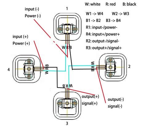
    This is the most common possibility and are used in may types of scales. Usually these 3-wire load cells are used in a combination such as 2 in parallel or 4 to make a bridge which would allow for a differential output approximately equal to mid-excitation supply. The load cell itself is similar to a voltage divider where the white wire is excitation +, the red wire is the junction of the voltage divider and the black wire as the excitation -connection. As strain is applied, one of the resistances change, which would result in a changing voltage across that resistance.

    So there are many possible configurations of this load cell(s) in the design. I still think that it would be possible to use the ADS122C04 for this system.

    Best regards,
    Bob B
  • Hi Bob

    Yes, Right. Now i got this. There will be combination of 4 bridge load cell to make it 4-Wire configuration. I have used this image for understanding, please confirm if this is right.

    As per image, R1---- > GND, R4---- > VCC, R2----- >  Sense + and R3------ > Sense -. Correct me if i am wrong.

    As per your recommendation, I saw datasheet of ADS122C04 and 5V is common for my both required load cell. So looks like i can use but still i have one concern.

    There will be some long cable so might be some voltage drop will be there. So, if possible any higher voltage Ic is available?

    Also, I can see this ADS122C04 Ic has only four channel means i can use only two Qty. of 4-wire load cell. In my use case, I need to use 4 Qty. of  4-wire load cell.

    So, can i get any Ic with 8 channel or i need to use two Ic of ADS122C04? But please keep in mind it should be with I2C only.

  • Hi Sumit,

    In your first post we had one load cell. In the second we had 2 load cells and now we have 4 load cells. Unfortunately we do not have a precision Delta-Sigma ADC for these kind of measurements that is I2C based and that many channels. You would have to use an external mux (which could add some error) or use two ADS122C04 devices.

    Best regards,
    Bob B
  • Hi Bob,
    I agree but first i was understanding and finding solution and then i realized part which you suggested that was not suitable for my second type of load cell so i mentioned second load cell.
    After that i told about Quantity. I did not get what is the issue here?

    Can you please check about 4- bridge load cell combination of 3-wire Load cell. That is right?

    I will plan for two ADS122C04 device.
  • Hi Sumit,

    There is no issue for me. I'm still waiting to hear the complete details of the design and the scale resolution that is required. This will make a huge impact as to what needs to be done in the system design. I really need to know the scale resolution to determine if the ADS122C04 will give you the needed performance.

    As far as the 3-wire load cell bridge, that appears to be correct.

    Best regards,
    Bob B
  • Hi Bob,
    Resolution is 0.5lbs that is 220 grams we can say.
    I found one part having part number ADS1234 and in this i can connect total 4 load cell. Only one concern i have and that is interface with host processor.
    Looks like this is not a standard interface. Only DOUT and SCLK is present so how it will get connect?
  • Sumit,


    Bob is out of the office for a couple of weeks, so I'll jump in with comments.

    The ADS1234 uses a DOUT (MISO) and SCLK similar to an SPI interface. Gain is configured through pin connections, and data is retrieved from /DRDY/DOUT through the falling edge of SCLK.

    The only difference is that there is no /SS so the master can only retrieve data for one device, and there is no MOSI because there are no commands to send to the device.


    Joseph Wu