This thread has been locked.

If you have a related question, please click the "Ask a related question" button in the top right corner. The newly created question will be automatically linked to this question.

TINA/Spice/ADC12DL3200: TINA/Spice/ADC12DL3200

Part Number: ADC12DL3200
Other Parts Discussed in Thread: TINA-TI, , LMK04828

Tool/software: TINA-TI or Spice Models

Dear Sirs,

I'm designing a board that uses two ADC12DL3200 connected at one FPGA Xilinx.

The FPGA downloads the data and drives the ADC12DL3200 control signals.

For example the SYSREF signal is driven by a LVDS FPAG Output.

Is it correct?

Is it possible to drive the SYSREF input signal with a LVDS driver (FPGA output)?


I'm looking forward to hearing from you.

Best Regards,

Daniele Sassaroli

  • Hi Daniele

    If you want to align or synchronize the data between the two ADC12DL3200 devices the SYSREF inputs must be driven in a way that is frequency locked and phase consistent with the 3200 MHz input clock to the ADC. The ADC output timing (data, clock and strobes) will be affected by the timing of the captured SYSREF signal.

    Using an LVDS output from the FPGA will likely not provide the phase alignment that is needed.

    As noted in the Clocking section of the ADC12DL3200 datasheet the SYSREF frequency is determined as follows:

    fSYSREF = fCLK / (LDEMUX + 1) x LFRAME x n

    where:

    • LDEMUX and LFRAME are register settings
    • fCLK is the device clock frequency at CLK+/-
    • n is any positive integer

    SYSREF will typically be generated using a clocking device similar to the LMK04828.

    I hope this is helpful.

    Best regards,

    Jim B

  • Hi Jim,

    thanks for your suggestions.

    In my case, I don't use the LMK04828. For this reason, I've asked 
    if i could drive the SYSREF with the LVDS driver.

    Could you help me?

    Thanks in advance.

  • Hi Daniele
    If you need to drive the SYSREF inputs from an LVDS driver you should AC-couple the connection. The SYSREF input common mode voltage must be between 0V and 0.55V. This is not possible using a DC-coupled connection from an LVDS driver.
    How will you be generating the frequency for the SYSREF signal inside the FPGA?
    Best regards,
    Jim B
  • Hi Jim,
    I will use a LVDS driver of a FPGA Xilinx Kintex-7.

    If you don't have a datasheet I will send you.

    Best Regards,
    Daniele Sassaroli
  • Hi Daniele
    The ADC12DL3200 SYSREF input will be compatible with that LVDS driver as long as you isolate the DC voltage using capacitors. You need to have a series capacitor between the + LVDS output and SYSREF+ input and another capacitor between the - LVDS output and the SYSREF- input. I would recommend a value of 4.7nF.
    Direct DC-coupled connections will not work, as the common mode voltage of the LVDS output is >0.55V.
    Best regards,
    Jim B
  • Hi Jim,
    thanks for your suggestions.

    I've a final question. I must insert the capacitors between the FPGA and the ADC12DL3200 - SYSREF inputs lines.

    Usually the LVDS lines require a 100 Ohm termination. It is need in this case or not?

    In my design, The SYSREF signal will be active only one time, after the power on.
    Then the SYSREF will be Always low. Is the AC coupling good solution for this type of use?

    I look forward to hearing from you.

    Regards,
    Daniele Sassaroli
  • Hi Daniele

    With AC-coupling, you will need to use SYSREF as follows.

    1. During system initialization a continuous 50% duty cycle signal will be output on SYSREF.
    2. After the DC voltage on the ac-coupling capacitors stabilizes, SYSREF processing can be enabled in the ADC.  (SYSREF_PROC_EN = 1, SYSREF_RECV_EN = 1)
    3. Optimum CLK to SYSREF timing can be set using the Automatic SYSREF Calibration feature and related controls.
    4. Once that has been used, and the ADC devices are both synchronized to the SYSREF signals they are receiving, then SYSREF processing should be disabled. (SYSREF_RECV_EN = 1, SYSREF_PROC_EN = 0)
    5. Once that is done the SYSREF signals can be set to static low.

    Please note that if you don't need to time-align the output signal timing between the 2 ADC12DL3200 devices in your system, then you do not need to use SYSREF at all.

    Best regards,

    Jim B

  • Hi Jim,

    thanks for your description.

    Maybe I have problems to manage this procedure in my design. One
    of the problems could be the time requested.

    Is it possible to connect in DC mode the SYSREF?

    In that case, Can I think that the operations and time will be reduced?

    Regards,
    Daniele Sassaroli

  • Hi Daniele
    The SYSREF inputs can be damaged if the applied voltage exceeds the limits in Table 6.1 Absolute Maximum Ratings of the ADC12DL3200 datasheet. The maximum positive voltage in that table is the lesser of 1.32V or VA11+0.5V. Since the LVDS DC output common mode voltage spec in the Kintex-7 datasheet shows a voltage range of 1.000V to 1.425V i think it is highly likely that damage could occur.
    In addition, if the common mode voltage is outside the limits listed in Table 6.3 Recommended Operating Conditions, the functionality and performance of the SYSREF capture is not known.
    Best regards,
    Jim B
  • Hi Jim,
    I read also the ADC12DL3200 and at page 12. It's declared that "DC coupling is required, in which case
    LVPECL input mode must be used (SYSREF_LVPECL_EN = 1)".

    If I use a LVPECL driver I will have DC coupling. Is it correct?

    I will want a DC coupling to avoid the stabilization time of the AC coupling. Is it possible?
    In the final application, the customer want change frequently the ADC clock and It's important
    to reduce time between the ADC clock change and the ADCs re-alignments/synchronization.

    Using a LVDS to LVPECL translator, I will change the SYS_REF format from LVDS to LVPECL!


    Regards,
    Daniele Sassaroli
  • Hi Daniele

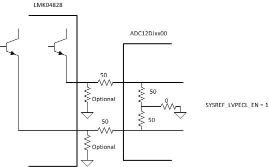
    Using an LVDS to LVPECL translator will enable DC-coupling the SYSREF signal to the ADC12DL3200 SYSREF inputs. The following termination circuit should be used to help match the common mode voltage between the LVPECL driver and the ADC.

    Also please ensure that SYSREF_LVPECL_EN = 1 before the translator is enabled/driving.

    Please also ensure that the SYSREF to CLK timing is consistent and meets setup/hold at all ADCs in the system.

    Best regards,

    Jim B

  • Hi Jim,

    thanks for your suggestions.

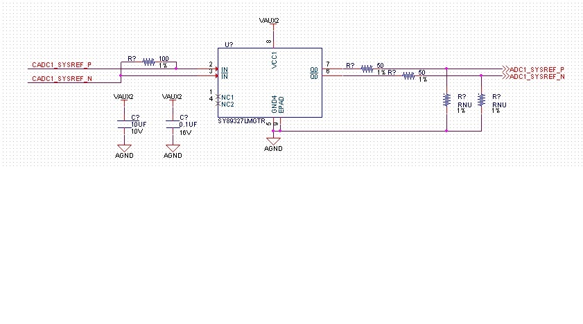
    I've inserted the circuit below to have the lvds to lvpecl translation for SYS_REF signal.

    Do you think is a correct solution?

    If yes, I will close the chat…..

    Regards,
    Daniele Sassaroli

  • Hi Daniele

    That may work. You may still need the additional resistors to ground from Q0 and /Q0 of the PECL translator. It would be best to include those in the circuit board design and if they are un-needed leave the components un-populated. 

    The goal is to satisfy the SYSREF VCMI and VID requirements of ADC12DL3200 datasheet Table 6.3 Recommended Operating Conditions. This is with the assumption that SYSREF_LVPECL_EN = 1 and there is 50 ohm termination to GND at SYSREF+ and SYSREF-.

    Best regards,

    Jim B