This thread has been locked.

If you have a related question, please click the "Ask a related question" button in the top right corner. The newly created question will be automatically linked to this question.

DDC264: DDC264EVM

Part Number: DDC264

The link on the product page for the DDC264EVM software download is not active. How can I get this software? I would have expected it included with the card. 

  • 3542.DDC264EVM.7zHi David,

    How are you?

    Thanks for using DDC264 EVM board.

    Please receive this file and try it.

    Thank you!

    Have a nice day!

    Best regards,

    Chen

  • I can't load the driver, windows says "Windows could not find the driver software for your device" even though I manually navigate to the drivers directory and there are files in the directory.

    I't's not clear that the file un-zipped correctly. It wouldn't unzip at all with WINZIP, so I tried the 7-zip file manager. However, I get an error "Warning: Can not open the file as [7z] archive. The file is open as [zip] archive. 

  • Hi David,

    How are you?

    Thanks for letting us know this issue.

    Yes, we would like to try to attach other one again.

    Hope this time it is working fine.

    Thank you again!

    DDC264EVM.zip

    Best regards,

    Chen

  • My latest try to reply bounced - I'm trying again. The install still doesn't work. I tried to point to the driver directory as suggested in the installation section and I still get the error:

    "Windows was unable to install you Unknown Device"

    "Windows could  not find driver software for your device."

     I attempted to install the software anyway and got the following error:

    Microsoft .NET framework

    "Unhandled exception has occurred .....

    Unable to load DLL USB_IOfo_VB6.dll. The specified module could not be found.

    Now what??

  • Hi David,

    How are you?

    Looks like you have already downloaded it and unzipped it at first.

    and then however when you tried to start to install it

    but you got some errors due to the Window's version.

    Right? 

    I would like to ask if someone knows the detail for this here

    and will let you know soon.

    Thank you

    and Have a nice day!

    Best regards,

    Chen

  • Hi David,

    Thanks for using DDC264EVM.

    According to our engineering manager here:

    Could you please copy the USB_IO_for_VB6.dll to the following

    directory location in your PC?

    C:\Users\<HostName>\AppData\Local\Apps\2.0\<XD0ROJ9A.HQL>\<00BDJN0E.MTC>\ddc2..tion_f0cdf37a7314ad51_0001.0000_542e76346161ac81

    The text highlighted in red could be different on the customer’s PC.

    This should most probably fix the error "Unhandled exception has occurred .....

     
    Please try it.

    Hope this can help.

    Thank you and best regards,

    Chen

  • Hi David,
    How are you?
    Just one thing can be different from yours is:
    This DDC264EVM software had been working only on Windows 7.
    (but not working on newer Windows system yet.)
    If you can try Windows 7 on your computer,
    then that would be great.
    If any question is still causing this software issue,
    could you please send us your email address?
    Thank you very much!

    Best regards,
    Chen
  • I still can't load the driver. When I try to "update driver software" from Device manager (by pointing to the driver directory for the eval card) it says that Windows can't find the driver. The software now runs after following your instructions, but it won't talk to the card without the driver.
  • You must have posted this while I was typing. Yes the PC uses Windows 7.
  • Hi David,
    Thank you for telling us more detail information.
    I need to forward your question to our system engineer.
    And will reply to you very soon in this week.
    Sorry for the inconvenience.
    Thank you!
    Have a nice day!

    Best regards,
    Chen
  • Hello David,

    I would like to take this conversation offline to help resolve the issue.
    Please send me an email at praveen.aroul@ti.com
  • Hi David,
    How are you?
    Thank you for letting me do more search for the solution for your issue.
    Actually you can look into TI E2E DDC264 on windows 7 fix issue as below:
    e2e.ti.com/.../2222724
    Hope this one can solve your problem.
    Sorry for waiting again.

    Happy New Year 2019!

    Best regards,
    Chen
  • It now LOOKS like it is communicating (it says Refreshed when you hit Refresh All), but the data is bogus and un-responsive. All channels read -3921.57, with or without the analog voltage applied. RMS noise all channels is 0.00. All LED's are on, it has a program and is connected to USB
  • Hi David,
    Thanks for letting us know.
    By the way, when you are running DDC264EVM
    you also need to connect an adapter (small-size) board onto it.
    Also could you also follow the DDC264 GUI?
    If still not working fine, could you please forward your reading (plots)
    to us?

    Thank you very much!
    Happy New Year!

    Best regards,
    Chen
  • Hi David,

    For testing DDC264EVM, please try the following example:

    Hope you can see very similar result:

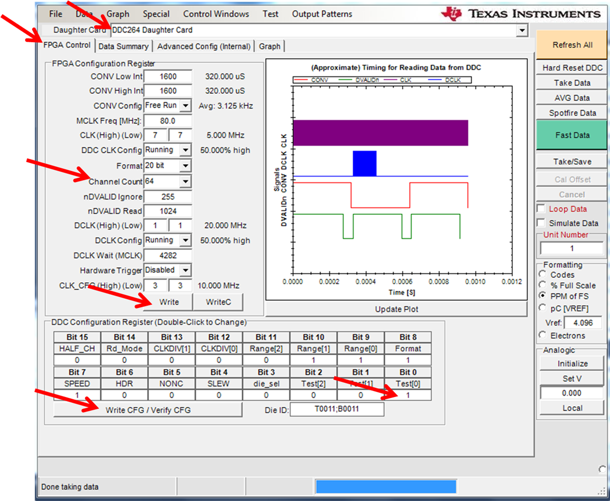
    1) Please set the FPGA Control:

    First, you can choose "Channel Count" to be 64 (only one DDC264 device=64 channels).

    Later you can change it to be 256 (totally 4 DDC264 devices=256 channels)


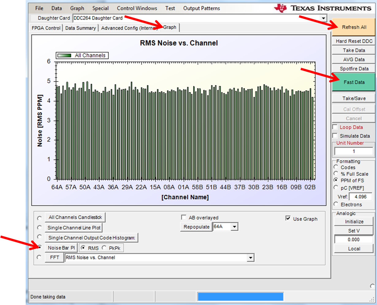
    2) Please select Noise measurement with Graph:

    Thank you for using DDC264EVM.

    Best regards,

    Chen

  • I did as you suggested. No change, I still get -3921.57 on all channels.
  • Hi David,
    How are you?
    Could you please provide us your pictures (plots)
    you received when you ran the DDC264 GUI?

    Thank you!
    Best regards,
    Chen
  • Hi David,
    How are you?
    Thanks for the pictures.
    When you get all the same data (for example: -3921.57) on all channels,
    that means DDC264EVM's output data are not correct.
    1) on the DDC264EVM, please press the following buttons:
    S1: REST
    S2: RST FPGA
    2) Please check on your EVM for the following jumpers:
    J19: JACK and 5V are connected
    J22: must be shorted
    J20: must be shorted
    3) the power connector (black) J18 must be connected to 5V dc.
    4) J12 and J5 are NOT used.
    5) please double check: J1 (USB connector) is connected to your PC.
    6) Please make sure: each time when you are using DDC264 GUI,
    after you click on "Write" button and "Write CFG/Verify CFG" button,
    then please must click on "Refresh All" button
    and finally click on "Fast Data" button.
    When click on each button, please wait until it is done
    and then you can continue to click on next button.

    Also when DDC264 GUI is running,
    please don't click on other GUI button
    until GUI displays "Done".

    Hopefully everything is working fine.
    Thank you!

    Best regards,
    Chen
  • There was some misleading information in the manual leading me to believe I could power everything from the USB cable. Not so. Got the power straightened out and started reading SOMETHING, but it's still not right. I patched a voltage source into the analog board (and set the appropriate jumpers for the patch. I only did the first bank of resistors) and tried to read the channel data while varying the voltage. I can read the correct voltage at the resistors on the analog board, but I don't get any change on the data read, other than changes in the noise level (and they are independent of the applied voltage). I went up to 5V with no effect. That's where I stopped.

  • Hi David,
    How are you?
    Sorry we don't know what happened to your settings as you mentioned,
    could you please send me more GUI pictures this time?
    Note: from the jumper connections, please follow exactly as we mentioned last time.
    If one jumper missing for not connected correctly. Then even the device set out any data
    but all the test data may not be correct at all.

    Thank you and best regards,
    Chen
  • The jumpers were configured exactly as required per your previous e-mail. Instead of jumper the missing jumper connection to provide the reference voltage I applied it to the provided jumpers on the analog card. The reference voltage was confirmed by measuring it at the resistors on the board. I used an ohmeter to confirm that the analog ground was connected to the main board. The jumpers were set so that voltage was only applied to the first bank of resistors. That's why you see me only monitoring the 1st channel in the graph. However, I confirmed that no other channel responded either.

  • Hi David,

    How are you?

    Could you please double check if you can setup your DDC264EVM as below?

    (We are using the following conditions to test):

    Thank you!

    (Please make sure all the LEDs are light on as shown below):

    Also one connector to Power and the other to USB to your PC.

    And note: these three Jumpers should be connected as below:

  • Yes - that's how it's connected and yes all the LED's are lit. I get new data each time I press Fast Data but it doesn't seem to matter what voltage I have. It always seems to stay right around .38% FS. One time it went up to 0.4% when I had 2V input, but then it went back down to .38% when I went to 3V and never changed again.

  • Hi David,

    How are you?

    As you mentioned about the different input voltage,

    what does it mean from using the DDC264EVM ?

    Does it mean power supply voltage by using J18 connector?

    Thank you!

    Best regards,

    Chen

  • As I confirmed earlier, J18 has 5V power applied to it. However, since the jumpers J15 and J16 are missing the analog reference voltage is not present at J11 of the analog breakout board. In order to have an input voltage I applied a voltage at J11. The correct pins were confirmed with an ohmeter and the provided schematic. The voltage applied at J11 appeared at the resistors, confirming that this was correctly wired.

  • Hi David,
    How are you?
    Please double check your DDC264EVM all the pins (including Jumpers and 5V Power supply) connection
    with the EVM picture I have shown you above.
    Because if there is something missing, the DDC264 GUI may still can run and capture data for you,
    however the data you just had captured may not be correct (maybe those bad data are misleading) at all.

    Also when you are running DDC264 GUI, after all the selections you have chosen,
    please make sure click on the following buttons by following such sequence below:
    1) Click on "Write" button (white button)
    2) Click on "Write CFG/Verify CFG" button (white button)
    3) Click on "Refresh All" button (yellow button)
    then, 4) Click on "Fast Data" button (green button)

    Hope these can help.

    Thank you and best regards,
    Chen
  • Hi David,

    How are you?

    First, we checked all three Jumpers:

    J19: shunt both Jack and 5V

    J22: shunt

    J20: shunt

    Secondly,

    We connect 5V power connector to J18

    Also, Yes, we followed your first plot with all the same settings as you did.

    After that, we did the followings:

    1) Click on "Write" button (white button)
    2) Click on "Write CFG/Verify CFG" button (white button)
    3) Click on "Refresh All" button (yellow button)
    then, 4) Click on "Fast Data" button (green button)

    After that,

    We checked the following two test results:

    To compare to the previous plots you sent to us:

    These two plots you can see are very similar to the results shown on the DDC264 User's Guide.


    Hope you can observe the similar test results.

    Thank you!

    Best regards,

    Chen