This thread has been locked.

If you have a related question, please click the "Ask a related question" button in the top right corner. The newly created question will be automatically linked to this question.

DDC114: How is output voltage not negative?

Part Number: DDC114

Hello,

I have a confusion about the operation of the DDC114 Analog amplifier stage.

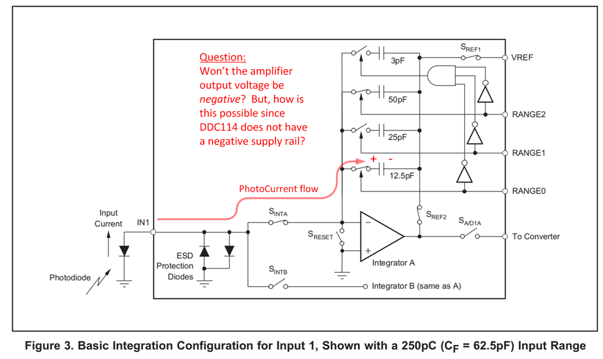
The datasheet shows the following circuit diagram for the input stage.  I have added the red text markups.

If the photocurrent enters the amplifier in the direction shown, won't it charge up the capacitor such that the amplifier will output a negative voltage?  However, there is no negative supply pin on this part.  So I do not understand how this device can measure photocurrent flowing in the direction that is shown.

Please explain, and sorry if i am missing something obvious.... !

  • Great question! The trick is that the during the RST phase, the feedback capacitor is actually charged to a certain value (not reset to zero). Hence the output of the integrator starts high and moves lower with the input signal. Please see figures 4 and 5 on the DS of the device for more details.

    Best regards,
    Edu
  • Hello Eduardo, 

    Thank you for your explanation!  This is helpful.  I understand now that the DDC114 resets the capacitor voltages to 4.096V before the start of integration.

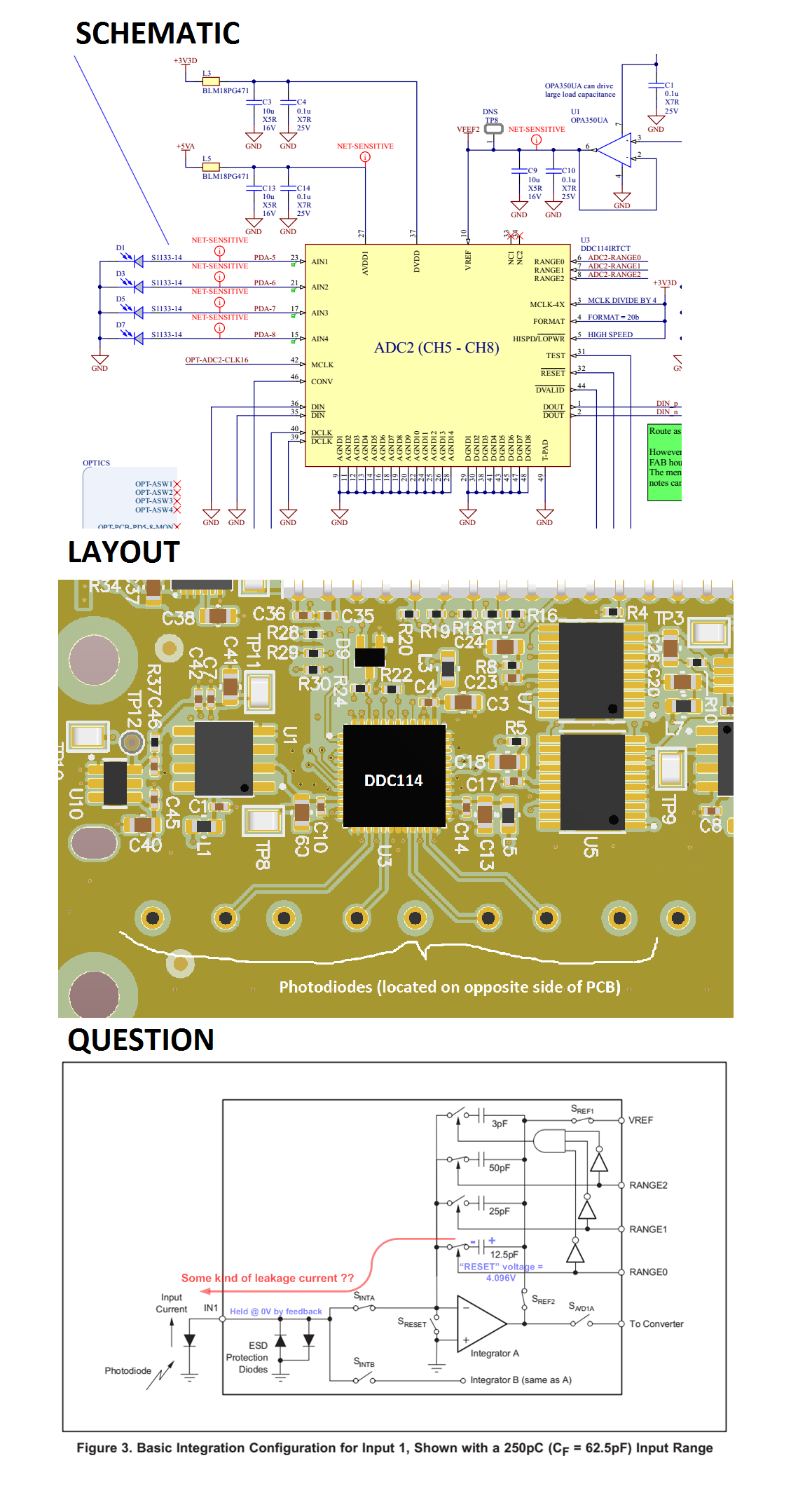
    We are having a strange problem on our system using the DDC114.  A snippet from our schematic is shown below. 

    Our layout looks as follows:

    On some boards, when we block all light to the photodiodes, we measure a value of all ZEROS from the DDC114.  According to the datasheet, this actually indicates slightly NEGATIVE current flow.  Does that mean that current is flowing as follows?

    If so, what could cause this kind leakage current?   We have NO negative power supplies on our board, so I am at a loss to explain where the leakage current might be going to.

    Could this be the result of a bad photodiode?  (But even so, with the photodiode biased to 0 volts, how could we ever see a leakage current?)

    Appreciate your help and advice.  Thank you,

    Mohan

  • Hi Mohan,

    What range are you using? Maybe you can observe the magnitude of that current by changing the range to bigger scales (you can also shorten the integration time) to avoid saturating...

    Also, what is the result with illumination? Do you get normal, linear behavior? Does this happens in all the channels? What is the result disconnecting the PD? You can try also the Test Mode.

    Overall I don't think the PD (or the DDC) are broken. Could be something else, like operation, some interferer (do you test your setup in a shielded box? although usually that shows with samples saturating low but also going the other way)... Can't see anything obvious on the design either.

    Regards,

    Edu 

  • Hi Mohan,

    Since we did not hear back from you, I am closing this post.
    If you have any further questions, please feel free to post them here or as a new thread.