Hi TI,
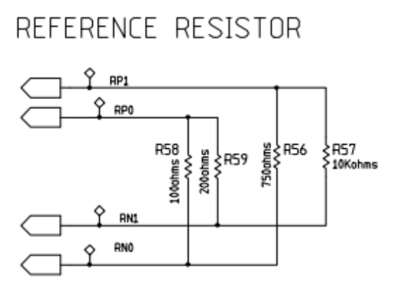
I have attached an image below of a simplified version of the reference resistor set-up that we are currently using:
This design is based on the the schematics provided by Texas Instruments in the AFE 4300 User Guide found here: (http://www.ti.com/lit/ug/sbau201a/sbau201a.pdf
I would appreciate the guidance on the questions below:
- In Section 2.1 of the Impedance Measurement instructions, titled SF-BIA Implementation using AFE4300 FWR Mode, the instructions reference only 2 reference resistors, Rx and Ry. However, the User Guide circuit schematic shows 4 reference resistors: R00, R01, R11, R10. Hence, I was wondering if the instructions within the Impedance Measurement sheet are designed for a circuit with 4 reference resistors and not 2 reference resistors, which the instructions imply? Should the instructions still work exactly the same if we are using the schematic shown at the top of this post? If not, how would it differ? Why do the instructions not mention the other two reference resistors?
- The instructions first state to "set the AFE4300 DAC frequency to 64 kHz", and then to "inject a 64-kHz frequency current and setting the data rate of the ADC to 64 SPS". First, could you show sample code specifically showing the registers you would set for DAC frequency and how you would set it to 64 kHz, and also how to set the data rate to 64 SPS? Secondly, does the injected frequency current refer to the excitation frequency? And I wanted to clarify if the instructions imply that we necessarily need to use a frequency for excitation that is the same as the DAC frequency (i.e. 64 kHz and 64 kHz)? What frequencies could I use if the DAC frequency is 64 kHz, could I use a excitation frequency of 20 kHz, or 50 kHz, or 100 kHz?
- The way we're currently using the 4 reference resistors now is: we use R00 and R11 to compute a slope and intercept.
However, instead of doing what the instructions state:
slope = (reference resistor value #2 - reference resistor value #1) / (observed ADC for #2 - observed ADC for #1)
We are currently using:
slope = (reference resistor value #2 - reference resistor value #1) / (computed mV for #2 - computed mV for #1)
To compute mV, we perform the following bit manipulation:
// r is data from ADC_DATA_RESULT, convert to mV
if (r & 0x8000)
   r |= 0xffff0000;
r *= 1700;
r /= 0x8000;
Do you see any issues with computing the slope this way? Would be great to sanity check this method. - As I mentioned above, the way we're currently using the 4 reference resistors now is: we use R00 and R11 to compute a slope and intercept. Then, we measure R01 and plug it into the calibration slope-intercept equation, and see if the output aligns with what we measure with a multi-meter. We then repeat the same with R10. Do you see any potential problems to this "test" of the calibration?
- While most of the ADC codes I'm getting are fairly consistent, I'm occasionally seeing ADC codes of 49584 and impedance values of -827.5878906 for the R00 resistor, when most of the time the same resistor reports an ADC code of 66. Can you think of any reason for this random and dramatic change? On a broader note, how consistent can we expect the ADC codes to be across different AFE 4300 chips, using the same circuit schematic?
Thank you so much for your help.


