This thread has been locked.

If you have a related question, please click the "Ask a related question" button in the top right corner. The newly created question will be automatically linked to this question.

ADS1294R: Bits Flickering in Lead Off registers

Part Number: ADS1294R
Other Parts Discussed in Thread: ADS1298R

Hi .

I am Vignesh From AKAS Medical.

We are using ADS1294R in patient monitor products. We observed below issues.

10 Machines are working well in a production lot. After few days 2 Machines displayed the Respiration rate values since the Lead off registers bits showing as "Connected" when ECG cable not connected to the patient or not connected to the Machine.

Issue No1:

When we remove/Connect the ECG cable from machine, the register values are given below when Comparator threshold 95% in Positive and 5% in Negative.

RA – 0

LA – 0

LL – 1

When we remove the ECG cable from machine, the register values are given below when Comparator threshold 70% in Positive and 30% in Negative.

RA – 1

LA – 1

LL – 1

Issue No 2;

ECG Cable is connected to the machine, We are observing the Lead off registers are getting flickering when the cable disturbed/Shacked in the below order.

RA – No Flickering Observed.

LA – Light Flickering Observed.

LL – Heavy Flickering observed.


What could be the causes for these problems?

  • Hi Vignesh,

    Thanks for your post!

    This is an interesting issue, my immediate thought is that there is a degradation of some sort in your signal chain and that the first case from Issue No1 and Issue No2 are related/caused by the same thing.

    Are you using the current souce or pullup/pulldown resistor method?
    What current magnitude are you using?
    What is your lead-off frequency?

    Were the machines being rigorously tested during the few days before the problem presented itself?
    Are the symptoms the same on both machines? Did the issues appear at the same time on both machines?
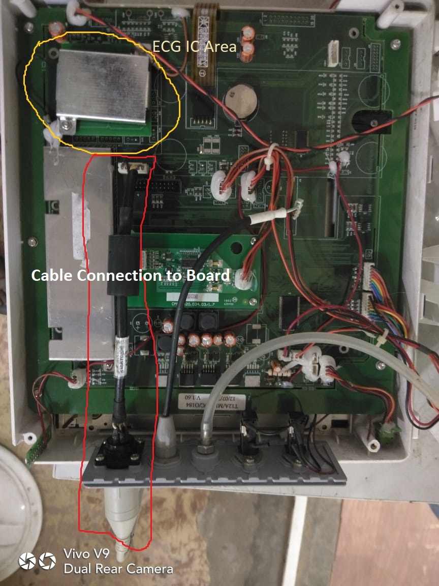
    What is the ECG cable connection to the board like? Can you take a picture?

    For the second case on Issue No1, is the reading correctly displayed with the ECG cable is connected?
    Is there any noise on the supplies?
  • Are you using the current souce or pullup/pulldown resistor method?

    We are using Current Source method for Lead off Detection.

    What current magnitude are you using?

    Initially 6 nA. Now Changed to 24 nA to faster Lead off detections.

    What is your lead-off frequency?

    LOFF - Register value is EF : Lead off Frequency is 11 : DC lead-off detection turned on

    Were the machines being rigorously tested during the few days before the problem presented itself?

    Yes, It was tested properly passed after 7 days testing.

    Are the symptoms the same on both machines? Did the issues appear at the same time on both machines?

    both the machines have same problem/Symptoms but time is different in both the machines.

    What is the ECG cable connection to the board like? Can you take a picture?

    Attached the picture of ECG Cable Connection to the board.

    For the second case on Issue No1, is the reading correctly displayed with the ECG cable is connected?

    Reading is displayed with graph properly when connected to the patient.

    Is there any noise on the supplies?

    There is no noise observed from Supplies

    Additional Observation From Failed Machines is ADS1294R Reference voltages -2.5V and +2.5V pins are getting shorted.

    In these machines ECG Graphs are not displayed when connected to the patients.

    Why the Pins are getting shorted after working 1 or 2 months good.

    How many channels(RA,LA,LL,Chest,RL) do we need to route to RL DSENSEP and  RLDSENSEN and what is the practical usage of this RLD in Lead off Detections.

  • Hi Vignesh,

    Can you provide a list of register settings in a table?
    Can you provide a schematic showing how the electrodes are connected?
    There is not a /-2.5 Voltage reference on the device. Do you mean power supplies when you say that they are getting shorted?
    How is this being measured?
    For now, disconnect all channels from RLD. Set all RLDSENS bits to 0.
  • 1   Register settings Details

    CONFIG1 0X 86

    CONFIG2 0X20

    CONFIG2 0XDC

    LOFF 0XEF

    CH1SET 0X50

    CH2SET 0X50

    CH3SET 0X50

    CH4SET 0X50

    RLD_SENSP 0X02

    RLD_SENSN 0X02

    LOFF_SENSP 0X06

    LOFF_SENSN 0X02

    LOFF_FLIP 0X00

    GPIO 0X00

    PACE 0X00

    RESP 0XF2

    CONFIG4 0X22

    WCT1 0XFA

    WCT2 0XE3

    2) AVDD (Analog supply) is short with AVSS(Analog ground).

    3).  Please find the attached schematic diagram.

    4.)  disconnect all channels from RLD. Set all RLDSENS bits to 0.

              We didn't observed any changes between connected and not connected to RLD. Power noise is reduced little bit When Channels are connected to RLD,       

    SCHEMATIC1 _ ECG _ELECTRODE_wtih Comments.zip

  • Hi Vignesh,

    AVDD (Analog supply) is short with AVSS(Analog ground) is a very big problem. Using probes, can you trace your power traces to the source of the issue? Are the rails established outside of the ADS1294R (is the short occurring inside or outside of the device?)
  • Hi Smith,

    Initially, the machines are working well for 2 to 3 months after production, after that in 5 out of 50 machines we observed like that.

    The Short observed in ADS1294R.  The Board is working fine when we replaced with new ADS1284R IC. What could be the reason for this problem?

    Did you verify the Register Configurations which i shared in the last post? Hope the configurations are fine. Kindly confirm the same to verify the Lead off Detection Bits flickering issue.

    Thanks and Regards,

    Vignesh N

  • Hi Vignesh,

    Originally you said after a few days 2 out of 10 failed. Now you are saying 5 out of 50 after a few months. Are you referencing failures from additional lots?

    There must be an issue with your power rails that causes an overvoltage condition which violates the absolute maximum ratings and leads to an internal short in the device. This could be a DC overvoltage or a transient protection issue - it is difficult to say without extended testing and knowledge of power supply circuits. I recommend looking into this extensively.

    I looked at the register settings to confirm that leadoff was enabled correctly, which it is. If AVDD and AVSS are shorted together that is a much bigger issue than the register settings.
  • Hi Smith,

    Thanks for register conformations. We will look into power sections and get back to you ASAP.

    Thanks and Regards,
    Vignesh N.
  • Hi Vignesh,

    How is your testing going?
  • Hi Tom,

    The PCB might be the problem for this case. we will confirm this based on the Hardware team verifications and testing which is going on.

    Thanks and Regards,

    Vignesh N.

  • Hi Tom,

    We are improving the Quality of PCB Regarding this ADS IC PRoblem. I will update the status once the new board test completed.

    Shall we derive Respiration Rate From RA-LA(Lead I) and RA-LL(Lead II) at same time using ADS1264R.

    Is there any configurations changes to use Below Multiple Respiration Derivation using this ADS1294R.

    RR From RA-LA
    RR From RA-LL
    RR From LA-LA

    Thanks and Regards,
    Vignesh N
  • Hi Vignesh,

    Looking forward to the testing results from your new PCB!

    I am not familiar with deriving the respiration rate from the leads.
    This video at 5:24 gives a brief overview of the respiration feature of the "R" devices: training.ti.com/how-measure-ecg-ads129x-product-family
    This app note gives a more in depth explanation of how the respiration rate is measured: www.ti.com/.../sbaa181.pdf
  • Hi Alex,

    Thanks for the documents and video which shared by you.

    I didn't observe like how to get Respiration Data from both RA-LA and RA-LL Combinations in ADS1298R at the same time.

    Could you discuss with your team and share the details of configurations or connection diagram of leads.

    Thanks and Regards,
    Vignesh N
  • Hi Vignesh,

    Happy to help!

    As I mentioned in my previous post, unfortunately I am not familiar with deriving the respiration rate from the leads.
    As shown in the app note, our devices calculate respiration using impedance pneumography. Please see section 1 Introduction, and Figure 1. Arrangement of Electrodes for Impedance Pneumography.

    If it is possible to derive the respiration rate from the RA-LA and RA-LL combinations, please provide the details for our own understanding.