Other Parts Discussed in Thread: ADS1293,
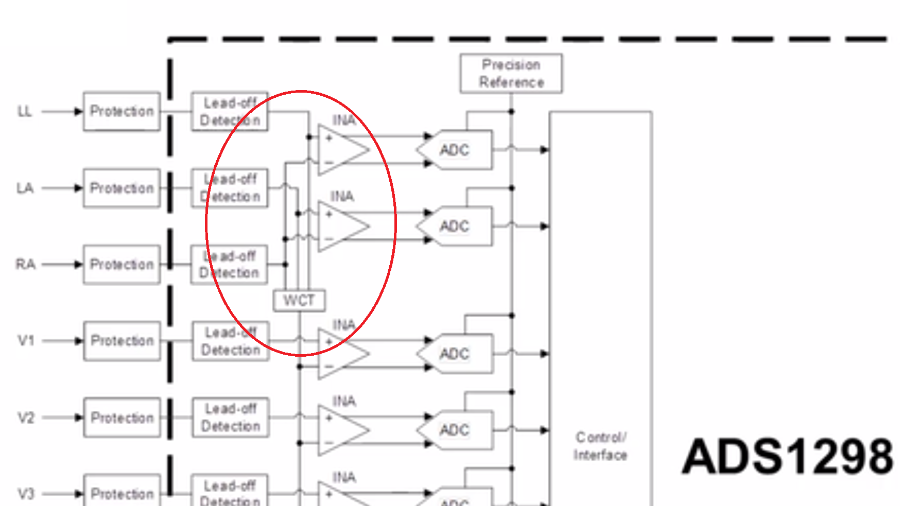
We are using the ADS1298 with 8 differential inputs, the primary use is for EEG measurements. However, one of the requirements is that our design shall be configurable to measure the standard ECG signals as well, i.e. Lead I, II and III and the Wilson connection. This requires the MUX of the device to be able to internally route the inputs from one channel to the INA of another channel. Specifically, the RA signal should be available on the negative input of two INAs to be able to generate LA - RA and LL - RA directly. An example of this is presented in the following training video;
"How to measure ECG - ADS129x product family
https://training.ti.com/how-measure-ecg-ads129x-product-family?cu=1128637
In this video (about 1.04 into the video) there is a figure showing 12-lead ECG with ADS1298. It shows that the RA electrode is internally configured to be routed to INA's of two different channels, to generate Lead I and Lead II (LA - RA and LL - RA, respectively).
However, I am not able to find out from the ADS1298 data sheet how to configure this routing internally. In section 9.3.1.3 Input Multiplexer (p. 27) or 9.6.1.6 CHnSET: Individual Channel Settings (p. 71) there seems to be no sign of this functionality.
So my question is whether it is actually possible to internally configure inputs from one channel to be connected to the INA of another, and if so, how is it done?
Interestingly, I see in the data sheet for another device in this family, the ADS1293, that it is described how to easily do this (p. 63-64).
Thanks for your help!


