This thread has been locked.

If you have a related question, please click the "Ask a related question" button in the top right corner. The newly created question will be automatically linked to this question.

[FAQ] ADS129x: How do I calculate the DC gain of the RLD or BIAS amplifier?

Other Parts Discussed in Thread: ADS1298, ADS1299, ADS1292, ADS1293

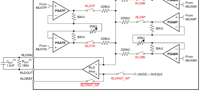
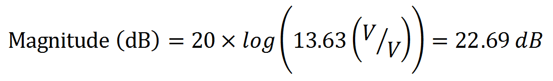
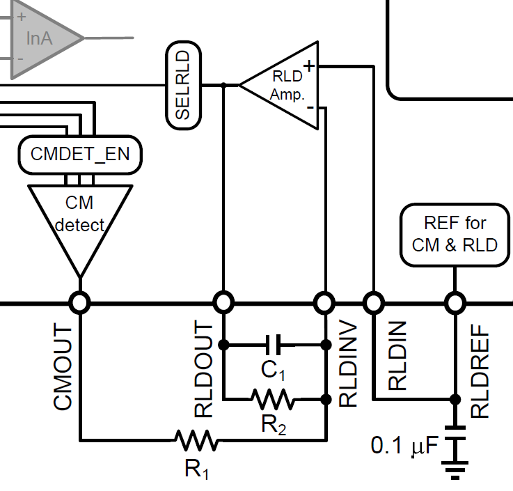
The DC gain of the RLD amplifier in ECG systems (or BIAS amplifier in EEG systems) may vary depending on the number of electrodes connected to the circuit and the surrounding components. So how can I calculate the expected gain for my system?

  • In the ADS129x family of bio-potential ADCs, each electrode input can be individually selected to derive the common-mode cancellation signal at the RLD/BIAS amplifier output. In the ADS1292, ADS1298, and ADS1299, these signals are connected to the amplifier's inverting input through a series resistor to form a summing junction. Below is an example from the ADS1298 datasheet:


    FIGURE 1: ADS1298 RLD Block Diagram


    The DC gain of the RLD/BIAS amplifier is then calculated by dividing the feedback resistor by the parallel combination of resistors connected to the summing junction. If 3 electrode inputs are selected (i.e. RA, LA, and LL), the gain would be calculated as:


    In the ADS1293, the summing junction is buffered by the CM Detect circuit before connecting to the RLD amplifier via an external resistor. This allows you set a fixed DC gain for the RLD amplifier regardless of the number of electrodes selected for common-mode derivation. In the figure below, the RLD amplifier gain at DC is set by R1 and R2  (suggested values are 100 kΩ and 1 MΩ, respectively).


    FIGURE 2: ADS1293 RLD Block Diagram


    Link to BIOFAQ homepage

    This post applies to ADS1191ADS1192ADS1291ADS1292ADS1292R, ADS1293, ADS1294ADS1294RADS1296ADS1296RADS1298,

     ADS1298RADS1299-4ADS1299-6, and ADS1299.