This thread has been locked.

If you have a related question, please click the "Ask a related question" button in the top right corner. The newly created question will be automatically linked to this question.

ADS8688: Problems starting conversion.

Part Number: ADS8688

I'm trying to use ads8688 with my BeagleBoard. The part responds to setting/reading registers, but starting conversions is a no go. AVDD is 5V, DVDD is 3.3V.

This is the python script I wrote:

#!/usr/bin/python

from Adafruit_BBIO.SPI import SPI

def ad_wreg(reg, d):
  r = spi.xfer2([reg*2+1, d, 0])
  if r[2] != d:
    raise Exception('error writing reg')

def ad_rreg(reg):
  r = spi.xfer2([reg*2, 0, 0])
  return r[2]

def ad_cmd(cmd):
  r = spi.xfer2([cmd,0,0,0]);
  return r[2:]

# --- main ---

spi = SPI(2,0)
spi.msh=100000
spi.bpw=8
spi.mode=1

ad_cmd(0x85) # reset program registers
ad_wreg(3, 3) # set features

for i in range(1,0x0d): # dump registers
  if i == 4: continue # no register 4
  print hex(i),hex(ad_rreg(i))

ad_cmd(0xa0) # auto_rst
print 'starting auto'
print 'cmd',hex(ad_rreg(0x3f)) # command read-back

for i in range(8):
  print i,spi.xfer2([0,0,0,0,0,0]) # no_op = auto_scan

spi.close()

The code produces the following output:

0x1 0xff
0x2 0x0
0x3 0x3
0x5 0x0
0x6 0x0
0x7 0x0
0x8 0x0
0x9 0x0
0xa 0x0
0xb 0x0
0xc 0x0
starting auto
cmd 0x0
0 [0, 0, 255, 255, 255, 128]
1 [0, 0, 255, 255, 255, 128]
2 [0, 0, 255, 255, 255, 128]
3 [0, 0, 255, 255, 255, 128]
4 [0, 0, 255, 255, 255, 128]
5 [0, 0, 255, 255, 255, 128]
6 [0, 0, 255, 255, 255, 128]
7 [0, 0, 255, 255, 255, 128]

I've verified the SPI signals with an oscilloscope. Everything looks fine. Furthermore, to rule out SPI glitches, I've set register 1 (AUTO_SEQ_EN) to every possible 8 bit value and read it back to verify. I.e. like this:

for i in range(0x100):

  ad_wreg(1, i)

  if i != ad_rreg(1):

    raise Exception('err')

I've done this several thousand times, no errors.

So the register writing/reading is ok, however starting a conversion, either with 0xa0 or 0xcx (for example 0xcc) always produces the above output. The command read back always returns 0. So at first glance, the chip will not start converting. However, inspecting the extra feature data (after the 16 bit result) seems to suggest more things are wrong. The channel address should change in auto mode, it does not. But ok, that can be explained with the chip not entering auto mode. The device address bits should be b00, since the feature register is 0x03, they're b11. The LSB of input voltage range should be b000, since the ranges for all channels are b0000, they're b111.

If I set feature to 0 the device will output:

[0, 0, 255, 255, 0, 0]

for all channels.

If I set feature to 1 the device will output:

[0, 0, 255, 255, 240, 0]

for all channels.

SPI mode is correct and I've tried all other modes. Mode 0 and 3 immediately fail at the register write/verify function, mode 2 works the same as mode 1.

I've now spent 3 days trying to figure this out with no luck. I'm ready to conclude the chip is malfunctioning. Help would be appreciated.

Oh, and commands do work, i.e. if I set some registers and then issue 0x85 command, the registers are returned to default.

Thank you,

Stewie

  • Hello Stewie,
    To address the issue you met, please start with Manual mode to convert a particular input channel by writing a valid manual channel n select command(MAN_Ch_n) in the command register as shown in Figure 83/84, please check the detail in section 8.4.2.6 and 8.5.1.
    A timing plot for /CS/SCLK/SDI/SDO captured with a scope will be very helpful, thanks.
    Regards
    Dale
  • Please refer to the example code on TI.com and the web link is shown as below:
    git.kernel.org/.../ti-ads8688.c

    Regards
    Dale
  • Hi Dale,

    Thanks for your help.

    As originally posted, MAN_Ch_n command produces the same output. Here's a plot of MAN_Ch_0 (0xc0), which has approx. 1.7V on it (3.3V divided in half by two 10k resistors), other channels are grounded. This is not the first 0xc0 command but one in a sequence of several, i.e. the data bits are from a previous 0xc0, not some unknown channel. Furthermore, 0xc0 followed by a NO_OP produces the same results.

    I have taken a look at the ti-ads8688.c before and haven't found any appreciable difference to what I'm doing.

    REFCAP is at 4.0953V.

  • Hi Stewie,
    Your timing looks clean, except some strange spikes on SDI, are you using virtual oscilloscope? can you please use lab oscilloscope to check? can you send your schematic to me for check? Your SPI mode 1 is correct because this ADC needs configuration(CPOL = 0, CPHA = 1) for SPI interface.
    Thanks&regards
    Dale
  • Dale,

    I used an Agilent DSO1024A, exported the signals to csv, converted to vcd and opened in GtkWave, a screenshot of which is what you see.

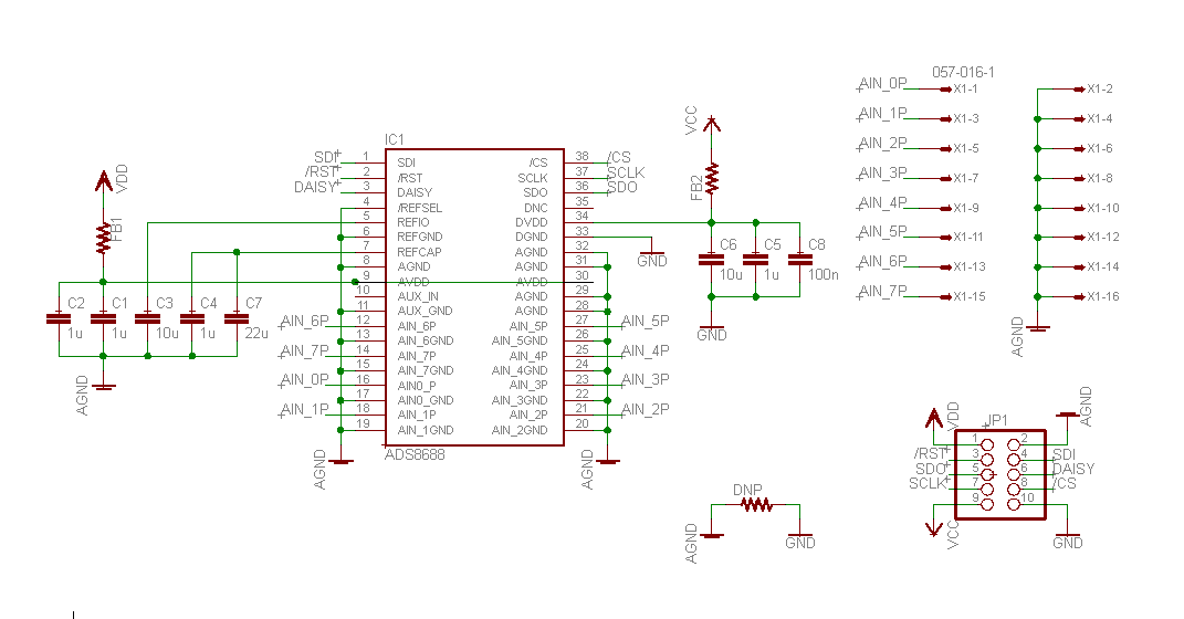
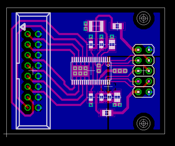
    These are the schematic and board view of my ads8688 daughterboard. Four of these plug into a carrier board, which,

    1. Ties RST of all daughterboards high.

    2. Routes Daisy between boards.

    3. Provides +5V to Vdd (analog supply) and +3.3V to Vcc (digital supply)

    4. Shorts AGND and GND.

    5. Connects daughterboards' SPI pins to BB's SPI via 100 ohm resistors.

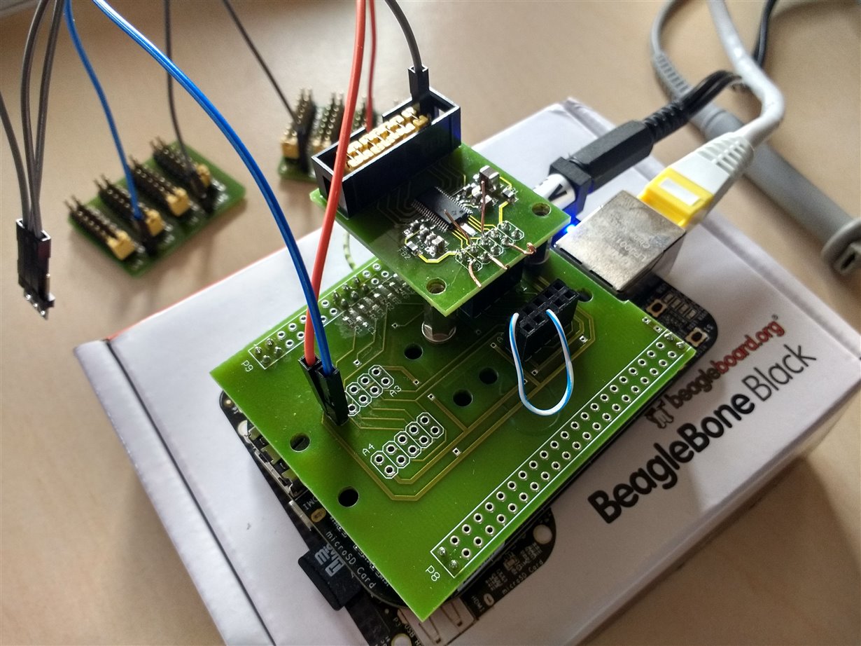
    This is a photo of my setup. The carrier board mounted on BB, with a single ads8688 daughterboard (last in the chain). The blue-white wire ties Daisy of the single daughterboard to GND. The copper wire stubs are where I connected the DSO probes. The two boards in the background are two decade resistor boards, currently set to 10k as mentioned.

    Thanks,

    Stewie

  • Hello Stewie,
    I will check and get it back to you soon, thanks.
    Regards
    Dale
  • Dale,

    Ok, so I made the thing work. Adafruit library was the culprit. It spuriously lowers /CS between transactions and I think that causes the chip to enter Frame abort condition.This was hard to find because I've only been looking at individual frames up to now and never between two frames. I've tried another library called python-periphery (github.com/vsergeev/python-periphery) and that worked immediately without issues.

    Thanks for your time.

    Stewie

  • Hi Stewie,

    Thanks for your update and clarification. Please let me know if your need any further support.

    Best regards

    Dale