This thread has been locked.

If you have a related question, please click the "Ask a related question" button in the top right corner. The newly created question will be automatically linked to this question.

ADS1298: ADS PROBLEM

Part Number: ADS1298

Good day,
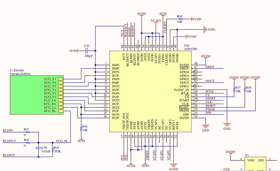
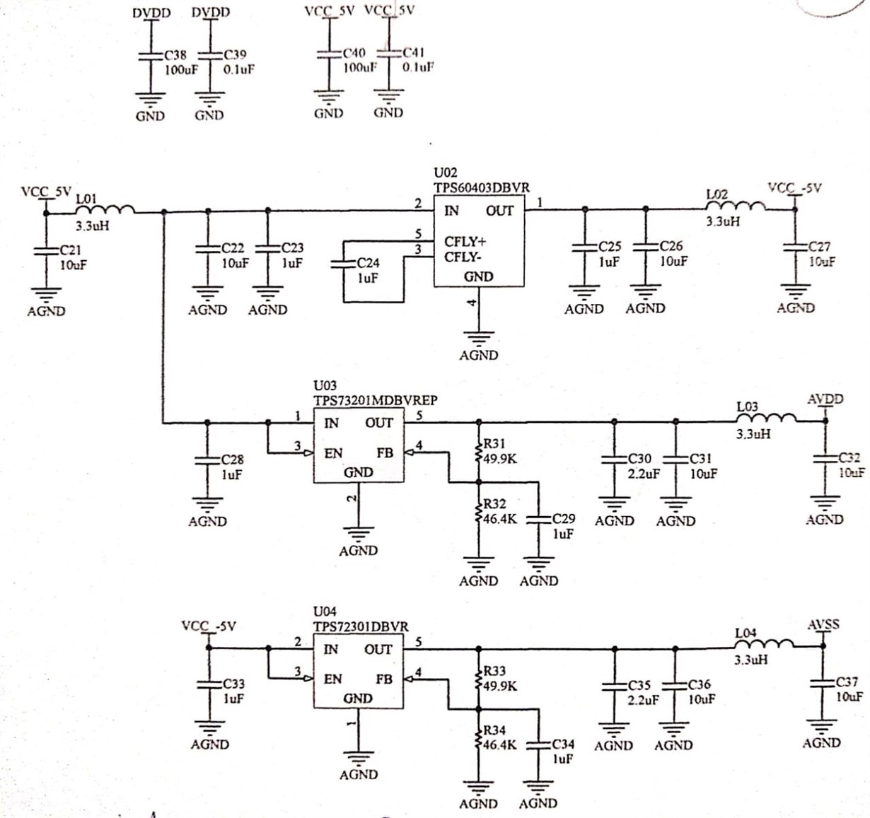
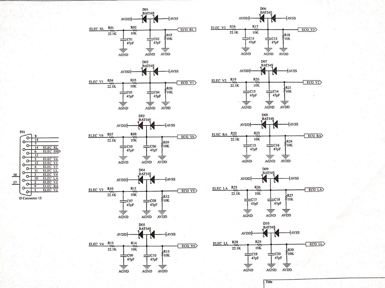
I want to show you a doubt regarding the ADS1298 and its right performance. The following is my schematic:

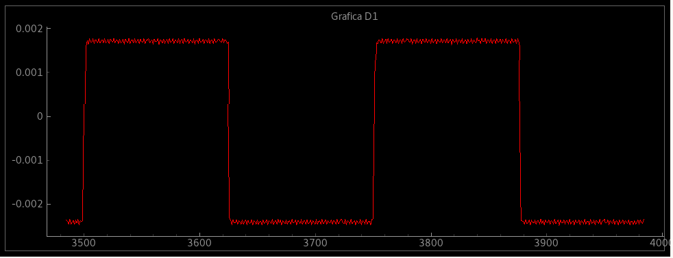
My design is supplied with AVDD= 2.5v and AVSS=-2.5v for a 5v total supply and configured with VREFP=4v. I have already aquired the ADS test signal with the following result:

My problem is, when I try to get the ECG signal through the 8 channels, it doesn't work, I get no result at all.

The configuration of the registers is the following:

Conf 1 = 0x86
Conf 2 = 0x00
Conf 3 = 0xEE
LOFF = 0x0F
Chan 1 al 8 = 0x01
Rld_sp = 0x03
Rld_sn = 0x03
LOFF_senp = 0xFF
LOFF_senn = 0x03
LOFF_flip = 0x00
Conf 4 = 0x02
WCT1 = 0x09
WCT2 = 0xD0
 
Any advice or recommendation for my ADS to work properly?

  • Hi Camilo,

    Thanks for your post and welcome to the forum!

    Are you able to read the device ID correctly?
    What does your data collecting routine look like?
    Are you sending the correct number of SCLKs for 8 channels of data?
    e2e.ti.com/.../2856884
  • Hi Alexander, thanks for your response.
    Answering your questions:
    1. Yes, I am. I have read the ADS ID record, obtaining a successful result with address 0x92 of ADS1298.
    2. Here is a screenshot with the data. It is written in Python, but the structure is the same in any language, I hope your comments in this section.

    #!/usr/bin/python3
    # -*- coding: utf-8 -*-

    from pickle import dumps
    import RPi.GPIO as GPIO
    import socket
    import spidev
    import time

    #Definiciones del Socket
    #host = '192.168.1.11'
    host = '192.168.43.5'
    port = 10000
    global sock

    #Sin alertas de GPIO
    GPIO.setwarnings(False)

    #Configuración de pines y constantes
    PIN_START = 6
    PIN_RESET = 12
    PIN_DRDY = 24
    PIN_CLKSEL = 23
    RDATA = 0X12
    SDATAC = 0x11
    RDATAC = 0X10
    START = 0X08
    STOP = 0X0A

    #Entradas y salidas
    GPIO.setmode(GPIO.BCM)
    GPIO.setup(PIN_START,GPIO.OUT)
    GPIO.setup(PIN_RESET,GPIO.OUT)
    GPIO.setup(PIN_CLKSEL,GPIO.OUT)
    GPIO.setup(PIN_DRDY,GPIO.IN,pull_up_down=GPIO.PUD_UP)

    #Inicializa SPI

    spi = spidev.SpiDev()
    spi.open(0,0)
    spi.lsbfirst = False
    spi.max_speed_hz=3000000
    spi.mode = 1

    #Inicio de variables
    GPIO.output(PIN_CLKSEL,GPIO.HIGH)
    GPIO.output(PIN_RESET,GPIO.HIGH)

    #Envio de datos
    time.sleep(0.1)
    spi.writebytes([SDATAC])

    #Inicializacion de Socket
    try:
    sock = socket.socket(socket.AF_INET, socket.SOCK_STREAM)
    print('El socket se creo correctamente')
    except socket.error:
    print('El socket no pudo se creado')

    try:
    server_address = (host, port)
    sock.connect(server_address)
    print('Conectando al servidor %s, por el puerto %s\n' % server_address)

    print('Conexion Exitosa!')
    except socket.error:
    print('El socket no pudo conectar con el servidor')


    #Funcion de captura
    def captura(channel):
    global datos
    global contador
    spi.writebytes([RDATA])
    resp = spi.readbytes(27)
    datos = dumps(resp)
    print('Datos: %s\n'%resp)
    print('Enviando datos...')
    sock.sendall(datos)
    #contador = contador + 1


    #Inicio de captura
    time.sleep(0.1)
    spi.writebytes([START])

    GPIO.add_event_detect(PIN_DRDY,GPIO.FALLING,captura)

    try:
    time.sleep(600)
    except KeyboardInterrupt:
    sock.sendall(dumps([]))
    sock.close()
    finally:
    GPIO.cleanup()
    sock.sendall(dumps([]))
    sock.close()

    3. Yes, I think I'm sending the correct data. I'm using Raspberry Pi's SPI interface to do it. I believe that the data is correct because I have been able to read and write several records at the same time, in addition, I have compiled test data that the ADS1298 generates by itself in the 8 channels, modifying the registers 1, 2, 3 and the 8 channels, evidence of this is the 4th image of the last post.

    I still have my problem which consists in, when I try to get the ECG signals through the 8 channels, I get no right result at all, so I am looking forward to your advise and support

    Thank you so much, Alexander.
  • Hi Camilo,

    Happy to help!

    I recommend closely reviewing figure 93, in the datasheet, Initial flow at power up.

    In the routine below, I do not see where you are waiting the appropriate times before sending additional commands. Additionally, it looks like GPIO.output(PIN_RESET,GPIO.HIGH) is attempting to toggle the GPIO pin connected to /RESET on the ADS1298, however looking at the schematic I see that /RESET is tied high to DVDD, not a GPIO. You will have to issue a /RESET command instead of toggling the GPIO if this is the case.

    #Entradas y salidas
    GPIO.setmode(GPIO.BCM)
    GPIO.setup(PIN_START,GPIO.OUT)
    GPIO.setup(PIN_RESET,GPIO.OUT)
    GPIO.setup(PIN_CLKSEL,GPIO.OUT)
    GPIO.setup(PIN_DRDY,GPIO.IN,pull_up_down=GPIO.PUD_UP)

    #Inicializa SPI

    spi = spidev.SpiDev()
    spi.open(0,0)
    spi.lsbfirst = False
    spi.max_speed_hz=3000000
    spi.mode = 1

    #Inicio de variables
    GPIO.output(PIN_CLKSEL,GPIO.HIGH)
    GPIO.output(PIN_RESET,GPIO.HIGH)

    #Envio de datos
    time.sleep(0.1)
    spi.writebytes([SDATAC])
  • Hello Alexander
    I have already followed his recommendations (I have made the adjustments on page 93 to test the correct behavior, get the test signals, all this with success).

    Regarding the sending time of several commands, as seen on page 63, in the section to send several commands, specify that, if the SPI interface used complies with tsDECODE, it is not necessary to send delays between the commands for ADS to work correctly, and in previous studies I determined that the Raspberry system's SPI interface meets this requirement, so I do not send the data as you suggest.
    Finally, I think it is true that the RESET is connected to DVDD but at a resistance of 10k which, in turn, is not connected with the ADS GPIO but the Raspberry GPIO and that is why I send the instruction GPIO.output(PIN_RESET,GPIO.HIGH), plus I have tried sending code for the RESET, findinf succesful results leaving standar registers, erasing these variables.
    In your opinion, what is the cause why I can not  properly sense through the required ECG signal ports, if I have succesfully collected the test singals? What is failing to collect the real signals?

    Best regards,
    Juan Camilo Caicedo España.

  • Hi Juan,

    If you're still using the register settings from the original post, your inputs are internally shorted. Try setting ChnSET register to 0x00h, as opposed to 0x01h.
  • Hello Alexander

    Thank you very much for attending to my messages. I have to apologize, I erroneously transcribed my code to publish it. I have 0x10 instead of 0x01, which means that all channels work correctly with a gain of 1, but it still does not work.

    I have done the exercise of putting in the differential input 2, a test signal of 1 mV which in practice are the RA and LA electrodes as the following figure shows:

    As I have metioned you in previews answers, I can not succesfully get the input signal which in this case is the one of 1 mV with 2 hz of frequency. I would like to ask you: Why is that? Perhaps a channel saturation? If so, how can I make sure the said saturation exists and how could I fix it? If it is not a saturation, perhaps could it be something related with the reference signal? In your opinion, am I configurating the reference signal properly? If not, how should I configurate it?

    Thank you once again for your help, Alexander!

  • If the channel was saturated it would produce a full-scale output. Since you can't get any output I'm not too worried about that.

    CONF3 Register has 0xEEh. You cannot use a 4V reference with +/-2.5V supplies.
    Set CONF3 bit 5 to 0... 0xAEh. Give this a shot.

    Try tracing the signal path using the block diagrams and multiplexor switching diagrams to make sure that the signal is correctly passing through. Disabling as many features as you can for now is also a good step.

    Additionally, you may want to check this post to verify that your device is functioning: e2e.ti.com/.../2868597