This thread has been locked.

If you have a related question, please click the "Ask a related question" button in the top right corner. The newly created question will be automatically linked to this question.

ADS1232: How to do a proper functioning test

Part Number: ADS1232

Hi, Best regards,

I have a ads1232 on a PCB connected to a microcontroller. Load of 10kg 2mV/V.

I set it to start reading in this way:

    PWDN_PIN = 0;
    SPEED_PIN = 1;
    SCK_PIN = 0;    
    
    __delay_ms(10);
    PWDN_PIN = 1;
    __delay_ms(100);
    PWDN_PIN = 0;
    __delay_ms(1);
    PWDN_PIN = 1;
    __delay_ms(1000);
    Calibration();              // 26 pulses after DOUT pin go to low, pulse width high 150ns and low 150ns
    __delay_ms(1000);   

Every time DOUT pin is low i shift 24 pulses to get the data and one extra pulse to send DOUT high.

The thing is that the values ​​obtained vary after few minutes without increasing weight in the load cell

I mean, the first data I take as reference offset, but a few minutes later this values increase o decrease without manipulate the load cell and it represent 3gr or more.

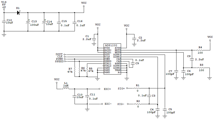
My schematic is based on ADS1232REF with the same filter input and reference voltages, capacitors, resitors and so on. Just with the different that DVDD is 5V, same as AVDD., on pin PWDN and SPEED a 47K Pull Down resitor and connected to the microcontroller, TMEP and A0 to ground, GAIN0 and GAIN1 to 5V.

What should be the correct value if i have the 10Kg, 2mV/V, gain 128, REF+ 5V, REF- GND, load cell without any weight?

How i can test the inputs AINP and AINN to see the properly values?

Thanks for your help.


  • HI Luis,

    Welcome to the E2E forum!  Most likely you are seeing some analog settling.  Can you send me your schematic for me to look at to determine how much settling time may be required?

    You are doing an offset calibration right away and this value might shift both due to analog settling and temperature drift as the device is warming up.  There will also be some settling of the load cell as well.  After say 5 or 10 minutes of operation, try running the offset calibration again to see if the values stay more stable.

    Another thing you may be seeing is noise.  Try capturing a series of samples and see if it appears that there is unexpected noise affecting the result.  If you can capture about 1000 contiguous and continuous data points and attach it to the post I can review it.

    Best regards,

    Bob B

  • Hi Bob,

    Thanks for your answer.

    This is my schematic and soon i hoope to get the data file with the readings, beacuse i just view this data in a LCD, then i'm going to send this readings to the laptop and capture in a file.

    I tryed restaring the ADS1232 without turn off the power supply. I mean after i see the values are change, i reset the MCU and  same bahavior after a few minutes.

  • Hi Luis,

    It would be very helpful to see the raw data from the ADS1232 prior to any data conversion to weight to help determine if there is a lot of noise in your system.  How are you restarting the ADS1232 without turning off the power supply?  Are you pulsing the PDWN pin?  Pulsing the PDWN pin will have the same effect as resetting the device.  However, you will need to reissue the offset calibration.

    When you see that the output is drifting does it eventually stabilize?  Or does it continue to drift?

    Do you have a long cable between the load cell and the ADS1232?  Is the cable shielded?

    The SPEED pin is defaulted low in the schematic, but do you ever set this pin high?  Do you see a significant difference between SPEED pin low (10sps) and SPEED pin high (80sps).

    As a baseline measurement, you could create a voltage divider using two 10k resistors from AVDD to gnd.  At the midway point of the two resistors you could short the AINP and AINN inputs together. This should give a consistent 0 V input and you should not see the output result drifting.  The result should stay within the value of the noise tables shown in the datasheet.

    Is there a particular reason why D1 is in your circuit?  Can you give me a part number for this diode?  I would suggest removing the diode and replacing with a short or 0 ohm resistor to see if that makes any difference.

    Best regards,

    Bob B

  • Hi, Bob

    I take in count your advice about warming up and seattling time of the device, and I decided do a review to the PCB and i found a really small piece of flux between inputs pins of the device, and even continuity and isolated test was good, but i think that was the problem, because i clean it with alcohol isopropilic and now is working good. The values are really stables.

    Really thanks for your help

    Best Regards.