This thread has been locked.

If you have a related question, please click the "Ask a related question" button in the top right corner. The newly created question will be automatically linked to this question.

ADS1293: ADS1293 3 Lead 3 channel without RLD

Part Number: ADS1293

Hi ,

How can we implement 3 electrode (only 3) and 3 channel ECG with only one ADS1293 ?

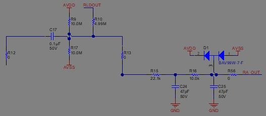
I saw a design that i found from this forum ;

  • What if we couple the rld with an another 100nf Cap but left side of the C17 ?

 Or couple with 5Mohm from left side of C17?

  • Why there is AVDD and RLDOUT coupled together in this design ?
  • What is purpose of R15,C24,R16,C25 ? Is this for filtering . I think D1 for clamping  to keep input between AVDD and AVSS .

https://e2e.ti.com/support/data-converters/f/73/t/828921?tisearch=e2e-quicksearch&keymatch=ads1293

  • Hello,

    Welcome to the E2E forum.  What is being described in the post you've referenced is an input channel for an AC-coupled receive circuit.  R12 connects the circuit to the ECG simulator, C17 is the AC coupling capacitor and then you can use either the AVDD/AVSS resistor divider, or the RLDout signal, to bias the input signal to mid-supply for the PGA/ADC in the ADS129x.  The post showed two option for the input signal biasing but you should only use one of the options, and RLDOUT is probably the preferred choice.

    R15/C24 and R16/C25 form low-pass filters.

    D1 clamps the input signal to within a diode drop of AVDD/AVSS to prevent over-voltage/under-voltage situations.