This thread has been locked.

If you have a related question, please click the "Ask a related question" button in the top right corner. The newly created question will be automatically linked to this question.

ADS1232

Part Number: ADS1232

Hi,

Firstly, I have used the ADS1232 in my project which works perfectly fine, but when I replicated the same board I face some problems which was new to me .

           XTAL 2 = GND or FLOATING ,

           XTAL 1 = GND,

INPUT =REF=5V,

GAIN0=0,GAIN1=0,SPEED = 0,

TEMP=0,A0=0,

,AIN0P=AIN0N=10mV,AIN1P=AIN1N=10mV,

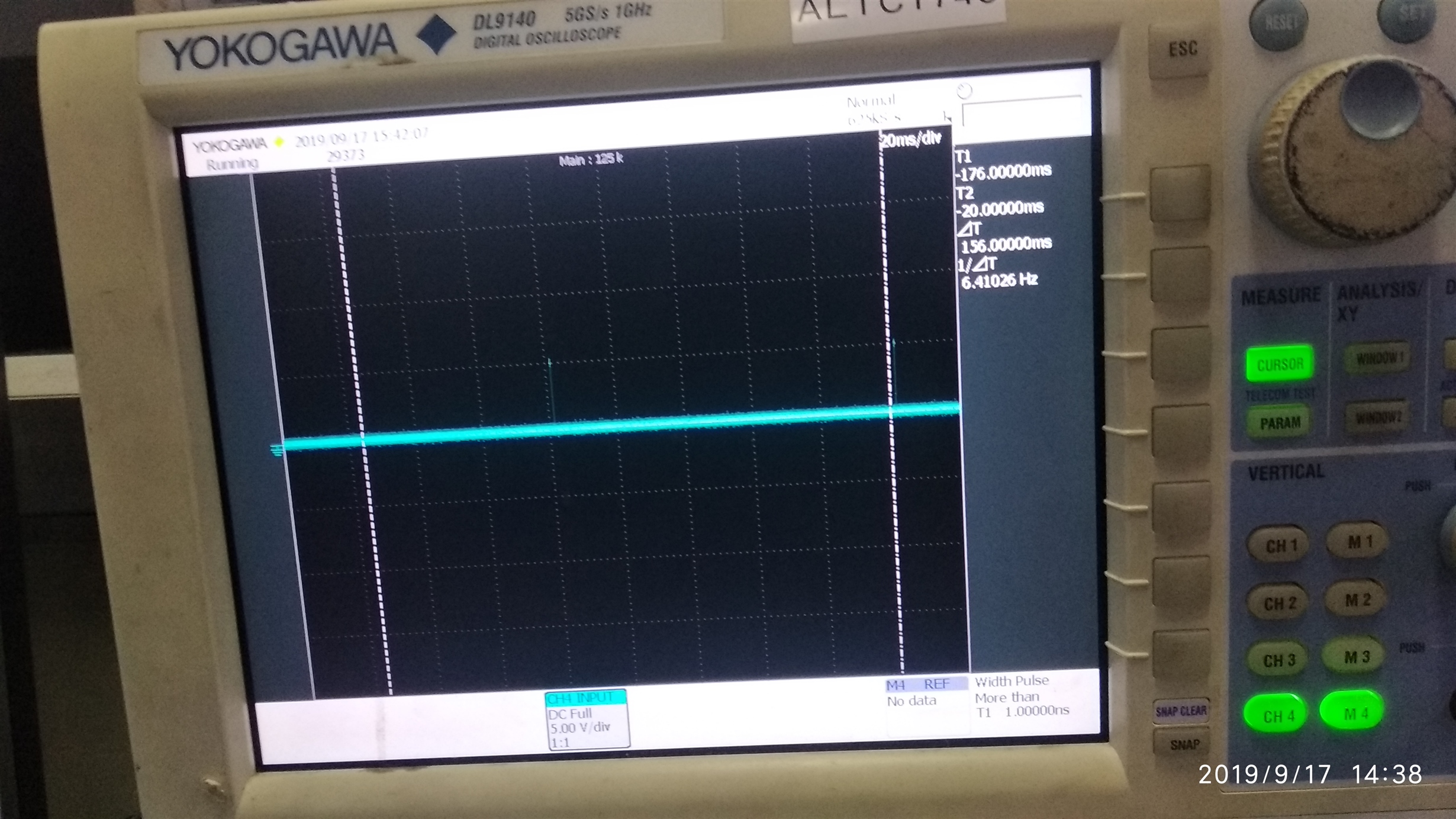
PDWN pin do HIGH LOW very fine at that I am giving SCK correctly  and my DOUT pin gives 10 SPS output where the output always seems to be in HIGH (+5V) .  I don't know what happens in my circuit , someone help me

Thanks in advance.

  • Hi Gobinath,

    You are setting the gain to a gain of 1, and the input voltage is the same for both inputs which should result in about 0V input.  What is the actual code value being returned?  Do you have a scope shot of the data being read from the ADS1232 that you can share?

    What are you using as an input voltage source? The input source must be reference to AGND of the ADS1232.

    The ADS1232 has a binary 2's complement output where 0xFFFFFF is actually -1 decimal. 

    Best regards,

    Bob B

  • I am using load cell as a input for two channels like

    Excitation(+)=10V

    Excitation (-)=AGND

    Signal(+) =AIN1P

    Signal(-)  =AIN1N (should I connect this pin to GND or what ? ) 

    Output of  DOUT pin is  0xFFFFFF .

  • Hi Gobinath,

    You are showing DRDY/DOUT which is indicating that the conversion is completing about every 100ms (10sps) which is how you have configured the ADS1232.  As you are not showing any SCLKs, I cannot tell what the data output is for the completed conversion.

    When DRDY/DOUT makes the transition from high to low, you should read the result by sending 24 SCLKs.  Can you send me a scope shot of DRDY/DOUT and SCLK (on the same scope plot) so I can see the actual data?

    Something else to note is if you are connecting a load cell to the input that is excited by 10V, the common-mode of the load cell is 1/2 of the excitation voltage which would be 5V.  This will be very difficult to measure at a gain of 1 or 2 (as you cannot use the higher gains due to common-mode restrictions).  You should excite the load cell with the same voltage as you power the ADS1232 analog supply.  You should also use this same supply as the reference voltage.  If you don't do it this way you will be subject to a lot of drift as the measurement is no longer ratiometric.

    The load cell is normally 4 or 6 leads when in a bridge configuration.  2 of them will be for excitation and 2 of them for a bridge output (and in the case of a 6 wire there will be 2 sense leads for the excitation supply to be used as the reference input).  The 2 bridge output leads would connect to the AINP and AINN inputs.

    Based on your configuration and question I suspect you have a load cell that is in a 3-wire configuration and not in a bridge configuration.  If that is the case you will need to create a Wheatstone bridge circuit with the load cell(s) as a bridge element(s).  The output of the bridge created would connect to AINP and AINN of the ADS1232.  You can find examples on how to build a bridge from 3-wire load cells by doing an internet search.

    Best regards,

    Bob B