


Other Parts Discussed in Thread: ADS1299, ENERGIA, MSP430FR5994,
Hi, I'm trying to set up ADS1299 from an Arduino UNO board. I'm currently using the OpenBCI C++ code posted on Github.
I tried to follow the initial flow at power-up (p. 62 datasheet), but I can't seem to obtain the proper SPI signals.
- The clock is set to 4Mhz, instead I get a 6Mhz signal
- DIN shows a periodic signal during RDATAC
- All SPI have different voltage offsets
Here I present the oscilloscope diagrams.
SCLK with DRDY:
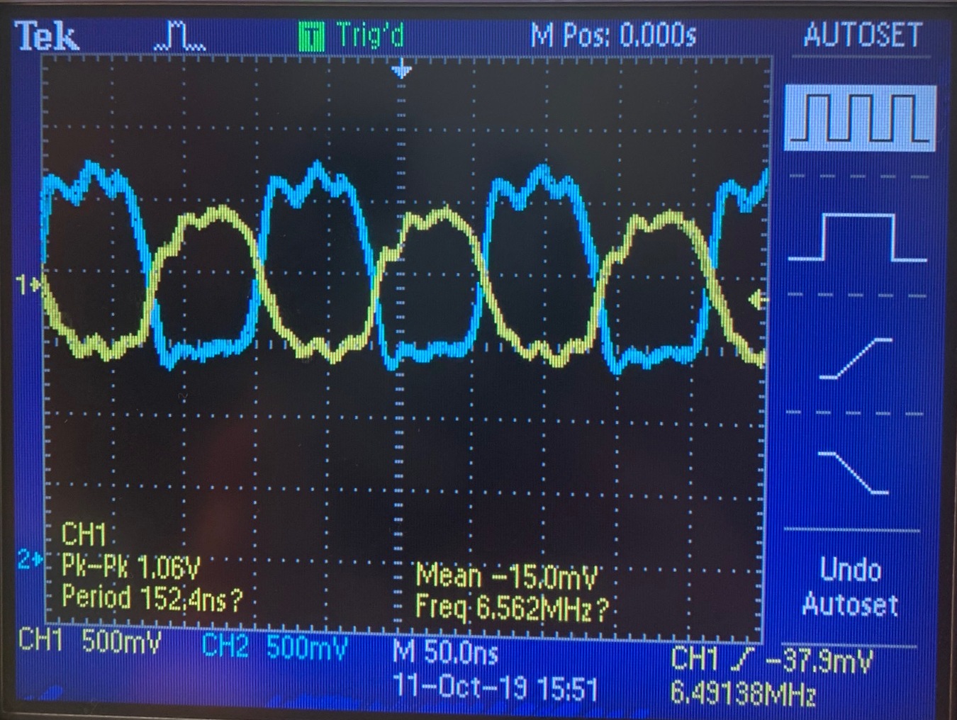
SCLK with DOUT:
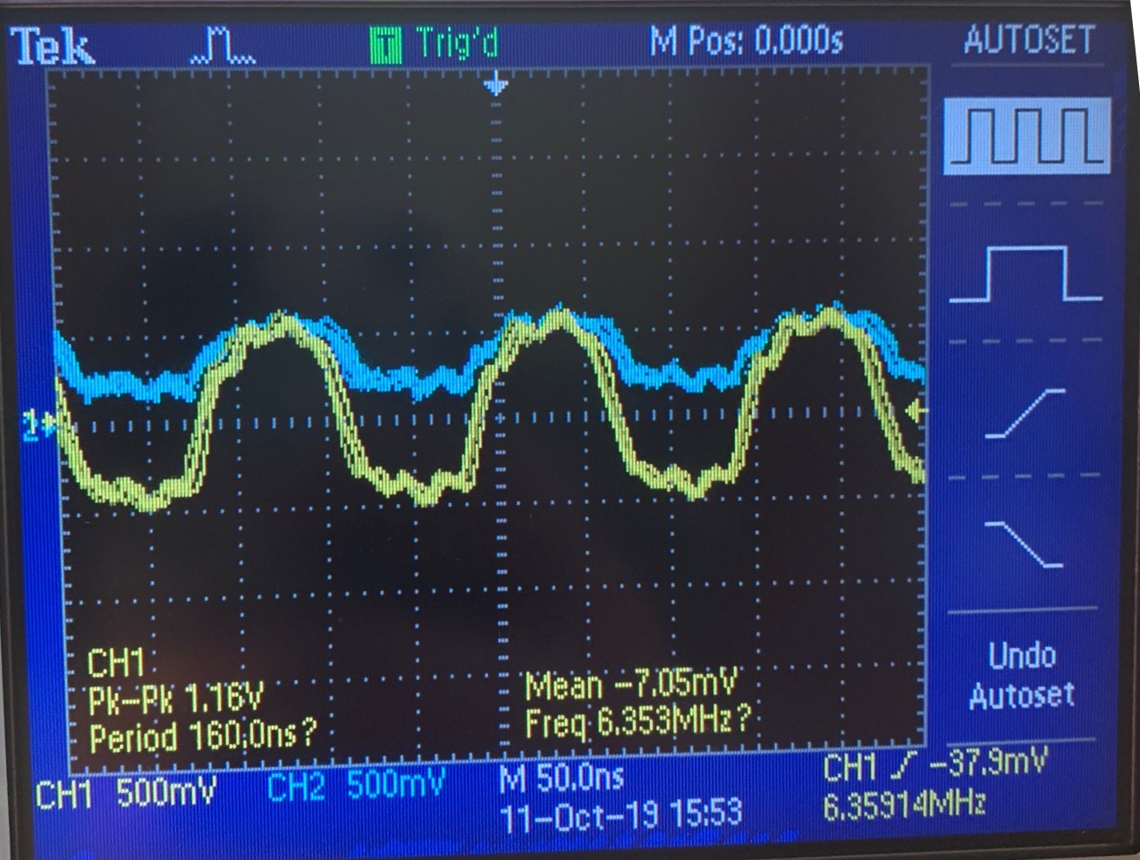
SCLK with DIN: shows the same signals, but with different offsets.
In addition, when I read the registers every few seconds they seem to change in random manner:
ID, 0x00, 0x82, 1, 0, 0, 0, 0, 0, 1, 0
CONFIG1, 0x01, 0x89, 1, 0, 0, 0, 1, 0, 0, 1
CONFIG2, 0x02, 0x93, 1, 0, 0, 1, 0, 0, 1, 1
CONFIG3, 0x03, 0x09, 0, 0, 0, 0, 1, 0, 0, 1
LOFF, 0x04, 0xBE, 1, 0, 1, 1, 1, 1, 1, 0
CH1SET, 0x05, 0x83, 1, 0, 0, 0, 0, 0, 1, 1
CH2SET, 0x06, 0x05, 0, 0, 0, 0, 0, 1, 0, 1
CH3SET, 0x07, 0x8A, 1, 0, 0, 0, 1, 0, 1, 0
CH4SET, 0x08, 0xCB, 1, 1, 0, 0, 1, 0, 1, 1
CH5SET, 0x09, 0x8B, 1, 0, 0, 0, 1, 0, 1, 1
CH6SET, 0x0A, 0xC5, 1, 1, 0, 0, 0, 1, 0, 1
CH7SET, 0x0B, 0x47, 0, 1, 0, 0, 0, 1, 1, 1
CH8SET, 0x0C, 0xF2, 1, 1, 1, 1, 0, 0, 1, 0
BIAS_SENSP, 0x0D, 0x3D, 0, 0, 1, 1, 1, 1, 0, 1
BIAS_SENSN, 0x0E, 0x01, 0, 0, 0, 0, 0, 0, 0, 1
LOFF_SENSP, 0x0F, 0xF0, 1, 1, 1, 1, 0, 0, 0, 0
LOFF_SENSN, 0x10, 0x1E, 0, 0, 0, 1, 1, 1, 1, 0
LOFF_FLIP, 0x11, 0xFE, 1, 1, 1, 1, 1, 1, 1, 0
LOFF_STATP, 0x12, 0xFF, 1, 1, 1, 1, 1, 1, 1, 1
LOFF_STATN, 0x13, 0xF8, 1, 1, 1, 1, 1, 0, 0, 0
GPIO, 0x14, 0x0E, 0, 0, 0, 0, 1, 1, 1, 0
MISC1, 0x15, 0x4F, 0, 1, 0, 0, 1, 1, 1, 1
MISC2, 0x16, 0xBE, 1, 0, 1, 1, 1, 1, 1, 0
CONFIG4, 0x17, 0x1E, 0, 0, 0, 1, 1, 1, 1, 0
ID, 0x00, 0x0C, 0, 0, 0, 0, 1, 1, 0, 0
CONFIG1, 0x01, 0x3F, 0, 0, 1, 1, 1, 1, 1, 1
CONFIG2, 0x02, 0x46, 0, 1, 0, 0, 0, 1, 1, 0
CONFIG3, 0x03, 0x2A, 0, 0, 1, 0, 1, 0, 1, 0
LOFF, 0x04, 0x93, 1, 0, 0, 1, 0, 0, 1, 1
CH1SET, 0x05, 0x60, 0, 1, 1, 0, 0, 0, 0, 0
CH2SET, 0x06, 0x14, 0, 0, 0, 1, 0, 1, 0, 0
CH3SET, 0x07, 0x37, 0, 0, 1, 1, 0, 1, 1, 1
CH4SET, 0x08, 0x0A, 0, 0, 0, 0, 1, 0, 1, 0
CH5SET, 0x09, 0x36, 0, 0, 1, 1, 0, 1, 1, 0
CH6SET, 0x0A, 0x20, 0, 0, 1, 0, 0, 0, 0, 0
CH7SET, 0x0B, 0xDF, 1, 1, 0, 1, 1, 1, 1, 1
CH8SET, 0x0C, 0xFE, 1, 1, 1, 1, 1, 1, 1, 0
BIAS_SENSP, 0x0D, 0xF4, 1, 1, 1, 1, 0, 1, 0, 0
BIAS_SENSN, 0x0E, 0x00, 0, 0, 0, 0, 0, 0, 0, 0
LOFF_SENSP, 0x0F, 0xFC, 1, 1, 1, 1, 1, 1, 0, 0
LOFF_SENSN, 0x10, 0x3F, 0, 0, 1, 1, 1, 1, 1, 1
LOFF_FLIP, 0x11, 0x1E, 0, 0, 0, 1, 1, 1, 1, 0
LOFF_STATP, 0x12, 0x00, 0, 0, 0, 0, 0, 0, 0, 0
LOFF_STATN, 0x13, 0x00, 0, 0, 0, 0, 0, 0, 0, 0
GPIO, 0x14, 0x7E, 0, 1, 1, 1, 1, 1, 1, 0
MISC1, 0x15, 0x1F, 0, 0, 0, 1, 1, 1, 1, 1
MISC2, 0x16, 0x00, 0, 0, 0, 0, 0, 0, 0, 0
CONFIG4, 0x17, 0x1E, 0, 0, 0, 1, 1, 1, 1, 0
I'm using a QFP64 TQFP64 to DIP64 Socket, a breadboard and jumpers.
This is the energia code:
#include <ADS1299.h>
ADS1299 ADS;
void setup() {
// don't put anything before the initialization routine for recommended POR
ADS.initialize(8,9,10,4,false); // (DRDY pin, RST pin, CS pin, SCK frequency in MHz);
delay(1000);
Serial.begin(115200);
Serial.println("ADS1299-Arduino UNO Example 1");
delay(1000);
ADS.verbose = true; // when verbose is true, there will be Serial feedback
ADS.RESET(); // all registers set to default
ADS.SDATAC(); // stop Read Data Continuous mode to communicate with ADS
ADS.RREGS(0x00,0x17); // read ADS registers starting at 0x00 and ending at 0x17
ADS.WREG(CONFIG3,0xE0); // enable internal reference buffer
ADS.RREG(CONFIG3); // verify write
ADS.WREG(CONFIG1,0x96);
ADS.WREG(CONFIG2,0xC0);
ADS.START();
ADS.RDATAC(); // enter Read Data Continuous mode
} // end of setup
void loop(){
delay(3000);
ADS.RREGS(0x00,0x17);
Serial.println("");
} // end of loop
_____
Extra information:
I tried changing the power source but I encountered similar problems. They also seem to happen during the initialization of the ADS but before the Serial.begin line which is very confusing. Could it be that I burnt out the chip or is it simply an SPI problem?
I appreciate your help!
Thanks!

