This thread has been locked.

If you have a related question, please click the "Ask a related question" button in the top right corner. The newly created question will be automatically linked to this question.

ADS1299: How to connect Bias amplifier to the recording channels in Referential Montage?

Part Number: ADS1299

Hello,

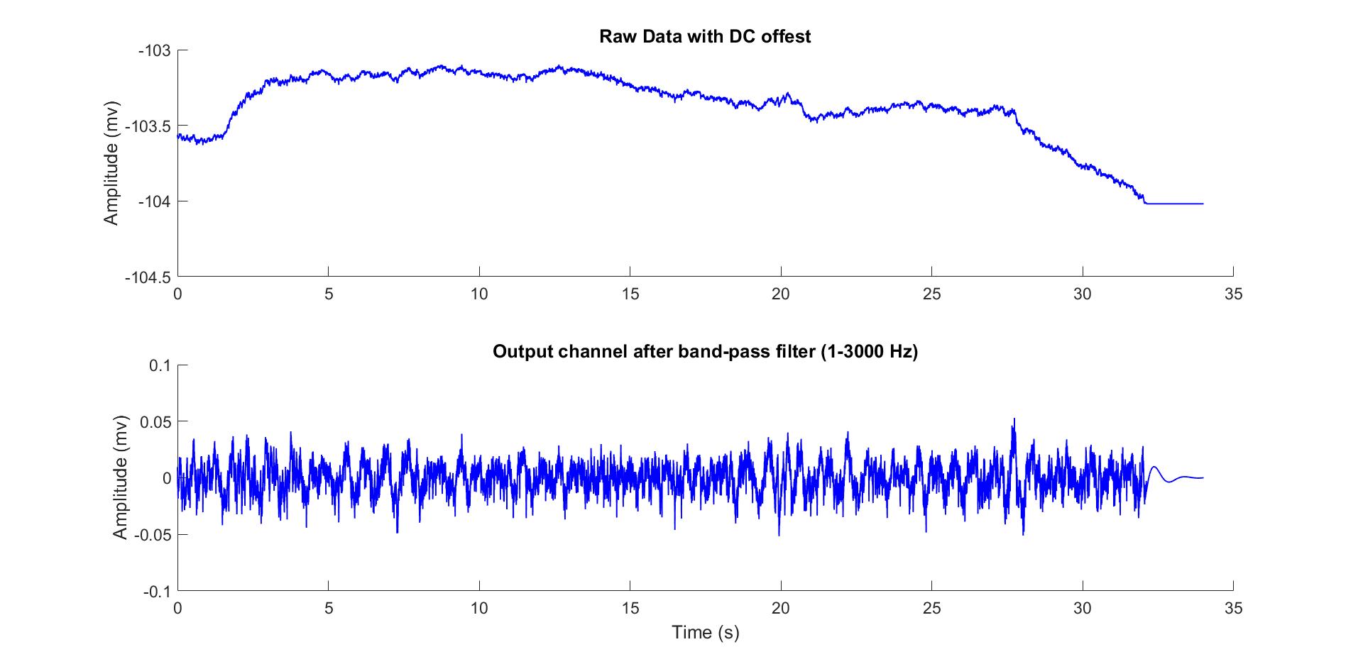
I am using ADS1299 ADC to record cortical signals (1Hz- 4000 Hz Bandwidth) with inside-brain implanted electrodes. I am successfully reading 8 channels with 8Ksps with gain 24 in referential montage. My main issue is bias signal on my channels that sometimes clips the output. As you can see in this picture, in 32 seconds the output has saturated because the input was bigger than Vref/ Gain =104 mv  (Vref=2.5, Gain=24)

My question is that,  can only adding AC coupling capacitor (series caps) on all channels  remove the DC offset?  If  yes why do we need to consider bias amplifier ? 

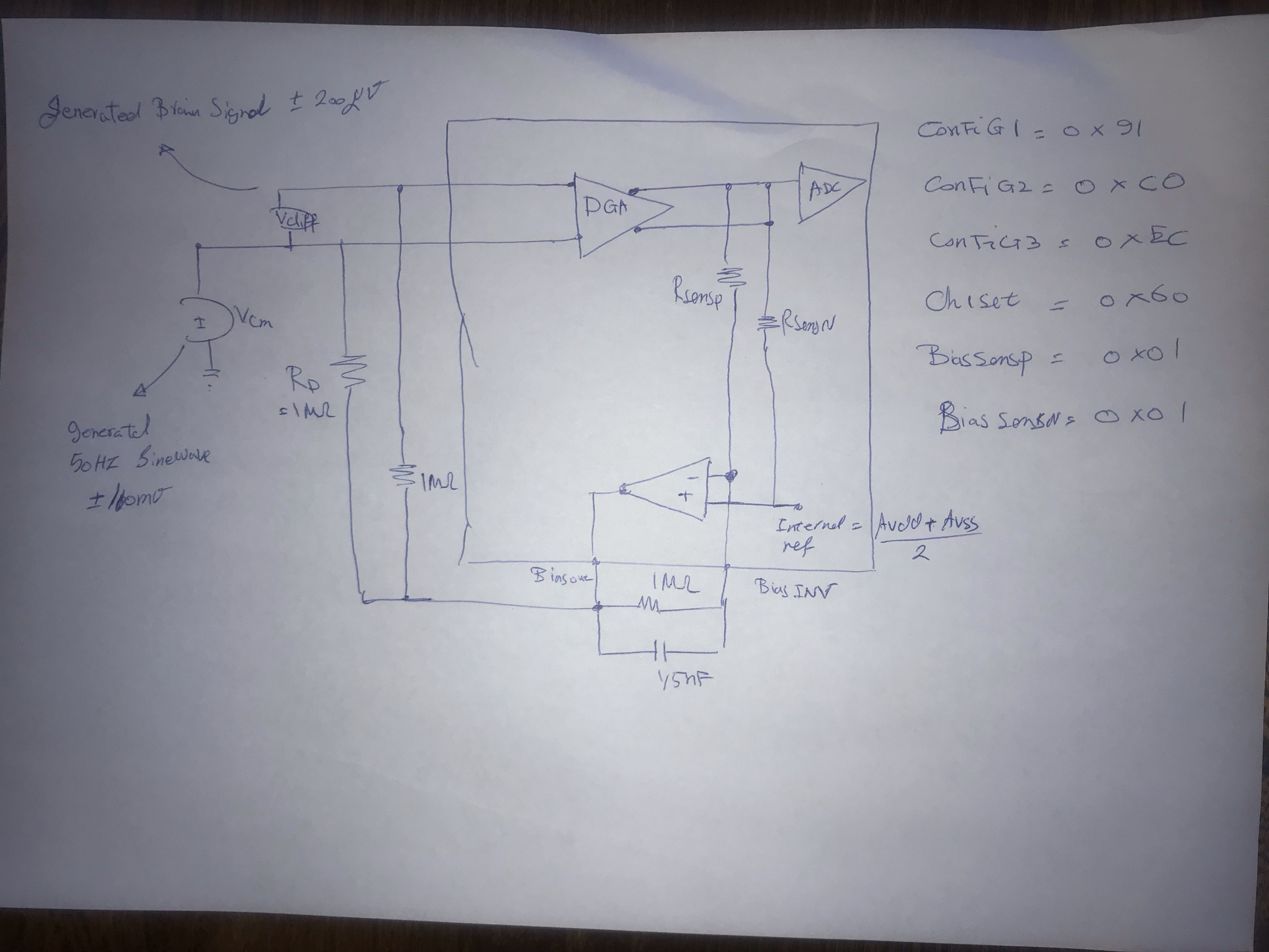
I have included a circuit for bias driver. I am going to activate the SENSP and SENSN bits of all channels to make an average common-mode signal and then connect the Biasout with below configuration. Is this a correct way to remove the DC offset.

I also do not understand the function of Multiplexing BIASN with input channels? Does it have the same function as the below configuration. 

Thank you,


  • Hello,

    Our ADS129x experts will get back with you early next week.

  • Hi Abed,

    Thank you for your post.

    First, a quick comment about the internal reference voltage. The ADS1299 internal reference is always 4.5 V. There does not appear to be an external reference voltage connected in your schematic, so I assume that's what you're using. This only affects the conversion from output code to volts, so the saturated output is equal negative full-scale, which is 4.5 V / 24 = -187.5 mV. 

    Although you have series capacitors which AC-couple the input signals, you may still develop an offset voltage from leakage current in the signal path. This includes the pull-up 10-M resistors. The tolerance of the 4.9-k and 10-M resistors will introduce some offset, which is then multiplied by the PGA gain.

    Since Channels 1-7 are unused in the schematic above, I would only enable BIASP8 and BIASN8 to derive the common-mode signal.

    The BIASIN function serves multiple purposes. Please refer to sections 9.3.2.4 of the ADS1299 data sheet.

    Best regards,

  • Hello Ryan,

    Thank for your great response.

    First, when I add capacitor in the input of channels it introduce noise in my output. Do you have any idea what does it happen? 

    To investigate the functionality of bias amplifier, I use the following circuit. As you can see I add 50 Hz, +-100mV sine wave to a brain signal generator  (input signal)(+-200 uv) . The Bias INV correctly shows the common-mode signal, but the Biasout signal (Measuring with Oscilloscope) is  not a sine wave common mode signal (it is a DC signal). Furthermore connecting Biasout to the input channels does not remove the common-mode signal. 

    The all configuration is shown in the below picture.

    Considering this design, do you have any idea why the bias amplifier does not work properly.

  • Hello Abed,

    Are you applying your signal to channel 1 or channel 8? Your schematic in the first post shows channel 8, but the register settings above refer to channel 1.

    The effect of the common-mode cancellation is observed by taking the ratio of the magnitude at the ADC output to the magnitude of the applied common-mode input. The signal at the ADC output will be whatever converted from common-mode to differential as the signal passed through the signal chain. 20*log10(ratio) gives you CMRR.

    There are some other useful application notes listed in the ADS129x BIOFAQ page below in my signature.

    Best regards,

  • Hello Ryan,

    I am connecting input to channel 1 in the new design.