This thread has been locked.

If you have a related question, please click the "Ask a related question" button in the top right corner. The newly created question will be automatically linked to this question.

AFE4490: ATE4490 SPI does not read

Part Number: AFE4490

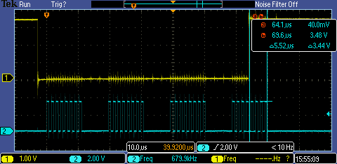
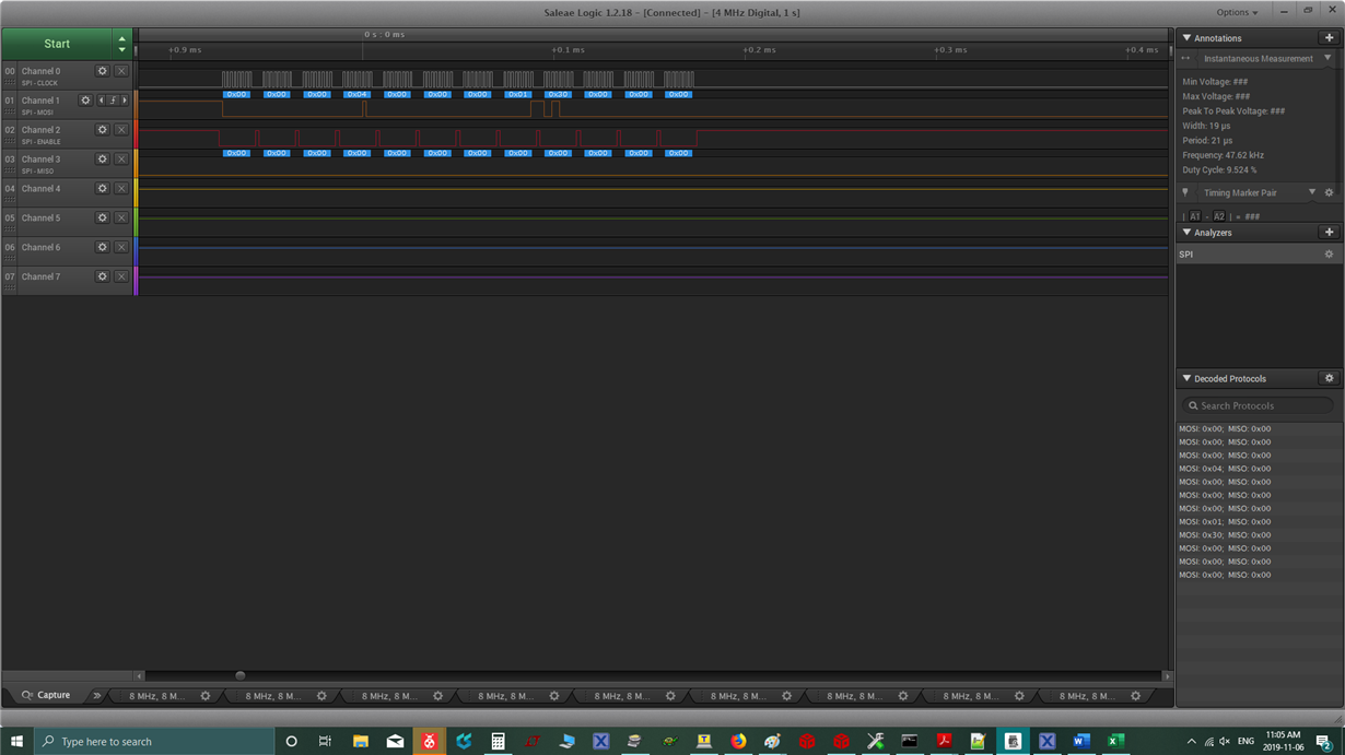
Hi guys, I am trying to read some registers from ATE4490 using NXP iMX RT1064 MCU. Please see the attached wave forms where you can see the clock in blue and MOSI signals in yellow. I am initially send this 4 byte to CONTROL0: uint8_t CONTROL0ReadBuffer[4]={0x00,0x00,0x00,0x0F}; right after I am sending other 4 bytes to read LED2VAL: buffer[4]={0x2A,0x00,0x00,0x00};

Could you please double check for me what am I missing my configuration. May SPI baudrate is around 100KHz; and I also verified that the reset pin( pin 20) and power down pi(pin 29) are pulled up high.

  • Any body can help on this please?

  • Hello Farid Mabrouk,

    1) Pin 20 is ADE_PDN
    2) Pin 29 is RESET
    3) If Diagnostic bit (DIAG_EN) is set (0x00[2:2]), the ADC data are invalid because of toggling diagnostics switches.
    4) If Software Reset bit (SW_RST) is set (0x00[3:3]), Software reset applied. Resets all internal registers to the default values and self-clearsto '0'

    Regards,

    Midhun Raveendran

  • could you please see the screen shot i just sent. I am trying to read from register DIAG( address: 0x30) but nothing is coming out: I am sending this set of data as seen in the screen shot: uint8_t buffer[12]={0x00,0x00,0x00,0x04,0x00,0x00,0x00,0x01,0x30,0x00,0x00,0x00};

    anything wrong with this packet( multiple write, read)? my SPI clock is 500KHz( is that too much)

    Please help me sort this out asap!!

    Cheers,

    Farid

  • Hello Farid Mabrouk,

      Inorder to read from Any register, you need to set the SPI_READ bit.

    Regards,

    Midhun Raveendran

  • Thank you all for your reply. I managed to fix the issue. I have to send 32 bits per frame. I was sending one byte at a time( CS needs to be low for the entire 4 bytes).

    I have another issue now: I am reading reasonable values for LED1VAL. However, I am reading 0x1FFF19 value all the time from LED2VAL register. I suspect this has to do with my default settings. Could anyone look at my settings below and tell me if they are right?

    static uint32_t AFE4490DefaultsRegs[49]= {
        //Reg0: CONTROL0: CONTROL REGISTER 0
        0x00000,
           //Reg1:REDSTARTCOUNT: SAMPLE RED START COUNT
        6000,
            //Reg2:REDENDCOUNT: SAMPLE RED END COUNT
        7599,
            //Reg3:REDLEDSTARTCOUNT: RED LED START COUNT
        6000,
            //Reg4:REDLEDENDCOUNT: RED LED END COUNT
        7599,
        //Reg5:AMBREDSTARTCOUNT: SAMPLE AMBIENT RED START COUNT
        0000,
        //Reg6:AMBREDENDCOUNT: SAMPLE AMBIENT RED END COUNT
        1599,
        //Reg7:IRSTARTCOUNT: SAMPLE IR START COUNT
        2000,
            //Reg8:IRENDCOUNT: SAMPLE IR END COUNT
        3599,
            //Reg9:IRLEDSTARTCOUNT: IR LED START COUNT
        2000,
        //Reg10:IRLEDENDCOUNT: IR LED END COUNT
        3599,
        //Reg11:AMBIRSTARTCOUNT: SAMPLE AMBIENT IR START COUNT
        4000,
            //Reg12:AMBIRENDCOUNT: SAMPLE AMBIENT IR END COUNT
        5599,
        //Reg13:REDCONVSTART: REDCONVST
        2,
        //Reg14:REDCONVEND: RED CONVERT END COUNT
        1999,
        //Reg15:AMBREDCONVSTART: RED AMBIENT CONVERT START COUNT
        2002,
        //Reg16:AMBREDCONVEND: RED AMBIENT CONVERT END COUNT
        3999,
        //Reg17:IRCONVSTART: IR CONVERT START COUNT
        4002,
        //Reg18:IRCONVEND: IR CONVERT END COUNT
        5999,
        //Reg19:AMBIRCONVSTART: IR AMBIENT CONVERT START COUNT
        6002,
        //Reg20:AMBIRCONVEND: IR AMBIENT CONVERT END COUNT
        7999,
        //Reg21:ADCRESETSTCOUNT0: ADC RESET 0 START COUNT
        0,
        //Reg22:ADCRESETENDCOUNT0: ADC RESET 0 END COUNT
        0,
        //Reg23:ADCRESETSTCOUNT1: ADC RESET 1 START COUNT
        2000,
        //Reg24:ADCRESETENDCOUNT1: ADC RESET 1 END COUNT
        2000,
        //Reg25:ADCRESETENDCOUNT2: ADC RESET 2 START COUNT
        4000,
        //Reg26:ADCRESETENDCOUNT2: ADC RESET 2 END COUNT
        4000,
        //Reg27:ADCRESETENDCOUNT3: ADC RESET 3 START COUNT
        6000,
        //Reg28:ADCRESETENDCOUNT3: ADC RESET 3 END COUNT
        6000,
        //Reg29:PRPCOUNT: PULSE REPETITION PERIOD COUNT  By default it is: 7999
        20000,
        //Reg30:CONTROL1: CONTROL REGISTER 1
        0x00107,  //timer enabled, averages=3, RED and IR LED pulse ON PD_ALM AND LED_ALM pins
        //Reg31:?: ??
        0x00000,
        //Reg32:TIAGAIN: TRANS IMPEDANCE AMPLIFIER GAIN SETTING REGISTER
        0x00000,
        //Reg33:TIA_AMB_GAIN: TRANS IMPEDANCE AAMPLIFIER AND AMBIENT CANELLATION STAGE GAIN
        0x00000,
         //Reg34:LEDCNTRL: LED CONTROL REGISTER
        0x11414,
        //Reg35:CONTROL2: CONTROL REGISTER 2
        0x00000, //bit 9
        //Reg36:?: ??
        0x00000,
        //Reg37:?: ??
        0x00000,
        //Reg38:?: ??
        0x00000,
         //Reg39:?: ??
        0x00000,
         //Reg40:: ??
        0x00000,
        //Reg41:ALARM: ??
        0x00000,
        //Reg42:REDVALUE: RED DIGITAL SAMPLE VALUE
        0x00000,
        //Reg43:AMBREDVALUE: Ambient RED Digital Sample Value
        0x00000,
        //Reg44:IRVALUE: IR Digital Sample Value
        0x00000,
        //Reg45:AMBIRVALUE: Ambient IR Digital Sample Value
        0x00000,
        //Reg46:RED-AMBREDVALUE: RED-AMBIENT RED DIGITAL SAMPLE VALUE
        0x00000,
        //Reg47:IR-AMBIRVALUE: IR-AMBIENT IR DIGITAL SAMPLE VALUE
        0x00000,
         //Reg48:DIGNOSTICS: DIAGNOSTICS FLAGS REGISTER
        0x00000

    Thank you!

  • Can any TI tech engineer reply to my question, please!

  • Hello Farid Mabrouk,

       Looks like the value you are getting is close to saturation. You can reduce the LED current and gain to come out of saturation and get expected value.

    Regards,

    Midhun Raveendran