This thread has been locked.

If you have a related question, please click the "Ask a related question" button in the top right corner. The newly created question will be automatically linked to this question.

ADS1198ECGFE-PDK: Elimination of 50Hz noise

Part Number: ADS1198ECGFE-PDK

Hi,

I recently purchased the ADS1198ECG-FE EVM for prototyping.

Although the board has RLD, ELEC SHIELD, I couldn't find clear instructions on how to eliminate the noise from 50Hz mains. This is greatly affecting the prototyping process.

In our current setup, we are using 5 electrodes where one of them connected to the AGND of the board as a gnd and the rest are used as channel inputs.

I appreciate your assistance on this,

Thanks

  • Hi Saba,

    Instead of having 1 electrode connected to AGND, connect this electrode to RLD. This will drive the inverted noise onto the body, canceling the 50Hz main noise. 

    Please see the BIOFAQ link in my signature below. There are several links that will help including a document explaining the theory behind common-mode rejection using RLD. 

  • Hi Alex,

    Thank you for your response.

    I went through the documents you sent earlier. However I am still not sure how to implement RLD in the EVM. I tried the following:

    1. Used the DB-15 EKG connector recommended for the EVM and attached RA, LA , LL along with RL so that I can observe Ch2, Ch3.

    2. Verified that the Channel Input is set to the Normal Electrode mode for Ch2, Ch3 

    3.Enabled the RLD Buffer (RLD Buffer Power = Enable) and the internal RLD reference (RLDREF Signal Source) in In CONFIG3 control register 

    4.Selected the electrodes for the RLD loop from the Right Leg Drive Derivation Control Registers controls
    (LOFF and RLD tab) - RLDP2, RLDP3, RLDN2, RLDN3  

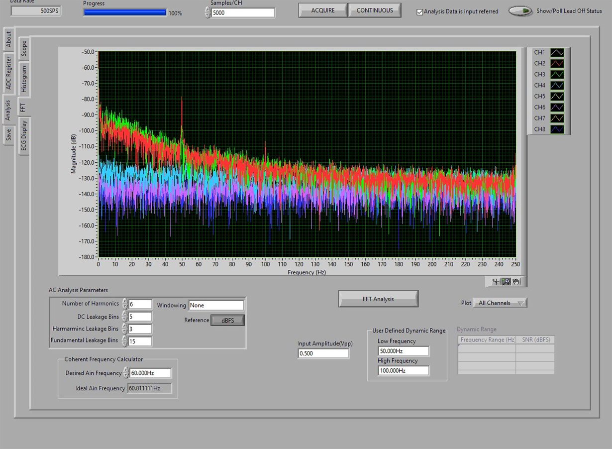
    And still I am getting the 50Hz noise as you can see from the FFT attached.

    AM I missing something?

  • Hi Saba,

    You can set normal electrode for all channels, enabling the RLD buffer and RLD reference is correct. 

    For your connections,

    Ch2 = RA - LL, Ch3 = RA - LA?

    I would like to confirm that you no longer have the 5th electrode connected to AGND? This essentially takes the noise that couples onto the body from the lights and directly injects it into the circuit GND.

    Let's confirm that the RLD is working. When you measure across R38, do you see a voltage near mid-supply? 

    If you set the RLD voltage to mid-supply instead of deriving from the input electrodes do you see mid-supply? 

  • Hi Alex,

    For my connections Ch2 = LA-RA and Ch3 = LL-RA according to the lead derivation.

    You are correct. I am using LA, RA ,LL and RL only. 

    I noticed that in the schematic of EVM (page 53 of ADS1198ECG-FE Datasheet) for some reason the bandwidth of the RLD loop was set to 46Hz. I haven't replaced the components yet. Do you believe increasing the bandwidth would solve this issue?

    I will test the mid-supply once I am at the office. 

    Thanks,

    Saba

  • Hi Saba,

    Excellent point, I forgot about this. I cannot guarantee that it will solve the issue, but it may help. With a cutoff of 46Hz I would still expect to see some attenuation of noise, but it is not ideal. 

  • Hi Alex,

    Thank you for the comments. 

    1. When I measure across R38 using DMM, I always see 0 voltage across R38. I believe that it is because of the bipolar configuration where AVDD =+2.5V and AVSS = - 2.5V. Voltage across R38 = (AVDD+AVSS)/2     Please correct me if I am wrong.
    2. How do I set the RLD voltage to mids supply instead of deriving from electrodes? Can this be simply achieved by disabling the RLD Sense bits?

    Thanks & Regards,

    Saba

  • Hi Saba,

    This is correct.

    It is in the register settings - I cannot check right now but if you continue to have issues let me know and I can check on my hardware. 

    Did increasing the bandwidth help with the measurement? 

  • Hi Alex,

    After increasing the bandwidth to 106 Hz, results improved but, still there are significant magnitudes for 50, 100 and 150 Hz components and the values were observed to be varying between the channels.

    Since the voltage across R38 is always 0, is there any other way to verify that the RLD loop is active? Also it would be much appreciated if you could check the register settings on your hardware.

    Thanks & Regards,

    Saba

  • Hi Saba,

    Glad to hear that it is improving. 

    Try changing to a uni-polar power supply configuration by switching jumpers on JP2 and JP20. 

    Changing to mid-supply is done by changing the RLDREF Signal Source in the CONFIG 3 register. You can see this on the third line of the ADC registers tab. 

    How are you connecting the electrodes? Are the connections secure? 

    Dry or wet? Is there hair at the connection point? Are you using sandpaper before applying the electrode? 

  • Hi Alex,

    Apologies for the delayed response. I didn't have the chance to try the above last week. Will definitely try your suggestions tomorrow and let you know the outcome.

    Regarding the connections, we are using DB-15 EKG connectors suggested by the EVM board manual and connected the ELEC_SHIELD to AGND(JP15 1-2). And we are using medical grade electrodes with hydrogel attached to the skin after removing the hair on it. We don't use sandpaper at the moment as it makes the person uncomfortable. 

    In the data sheet, I noticed the ELEC_SHIELD can be driven by the RLD(In phase/ out of phase). Does it make a significant reduction in the interference when using RLD as the ELEC_SHIELD rather than AGND? I haven't tried the RLD shielding as it requires some additional components.

    Thanks & Regards,

    Saba

  • Hi Saba,

    Those connections should be fine. Yes - sandpaper is quite uncomfortable and typically only necessary for the very long tests. 

    It really depends on the system and environment that is being operated in. For the highest performance, yes the shield should be driven - but acceptable performance should be possible without it. 

  • Hi Alex,

    Thank you for the feedback, Although I couldn't test the RLD loop functionality, the FFT showed significant reduction in the 50Hz component when switching to RLD from AGND connection. 

    Thank you for your detailed support, I really appreciate it.

    Kind Regards,

    Saba