Hi,
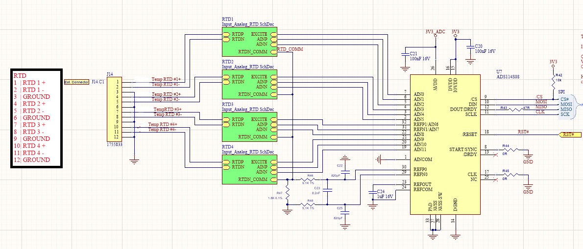
We are running into an issue with this ADC where the device returns bad measurements after running for a period of time. The ADC is set up to sequentially read 4 RTD channels. The schematic is linked below.
I have also linked the device register configuration. Through the operation of the device we periodically change INPMUX, IDACMAG, and IDACMUX to configure different channels for a single shot conversion. This is done by writing the register and then subsequently reading the register to confirm its state has been properly changed. This works well for a large number of the systems that have been produced. A number of the systems have experienced a failure point where the ADC no longer returns measurements that reflect the RTD values. It could be 0 or MAX returned. I now have one of the units with this behavior and am running tests trying to isolated the cause.
I was surprised to see that the registers seemed to be correct even while the device is failing. We have suspected that some communication noise might be causing this issue, but have been unable to isolate any.
The one register that is interesting is the STATUS register. This POR bit is never cleared in the firmware and we never write to that register. On the failed chip, this bit was cleared. It is worth noting that a software reset command plus re-initializing the device registers fixes this issue.
Have you seen any issues like this before or do you have suggestions related to this?
Thank you for any help!
Best,
Eddie
|
REG |
NAME |
Default |
Failed State |
Expected Initialization (by inspection of code) |
|
00 |
ID |
0C |
0C |
|
|
01 |
STATUS |
80 |
00 |
|
|
02 |
INPMUX |
01 |
-- |
|
|
03 |
PGA |
00 |
00 |
00 |
|
04 |
DATARATE |
14 |
37 |
37 |
|
05 |
REF |
10 |
02 |
02 |
|
06 |
IDACMAG |
00 |
-- |
|
|
07 |
IDACMUX |
FF |
-- |
|
|
08 |
VBIAS |
00 |
00 |
|
|
09 |
SYS |
10 |
11 |
11 |
|
0A |
RESERVED |
00 |
00 |
|
|
0B |
OFCAL0 |
00 |
00 |
|
|
0C |
OFCAL1 |
00 |
00 |
|
|
0D |
RESERVED |
00 |
00 |
|
|
0E |
FSCAL0 |
00 |
00 |
|
|
0F |
FSCAL1 |
40 |
40 |
|
|
10 |
GPIODAT |
00 |
00 |
|
|
11 |
GPIOCON |
00 |
00 |
|
Continuously updated and checked after each channel is sampled.


