Other Parts Discussed in Thread: ADS1298R
howdy!
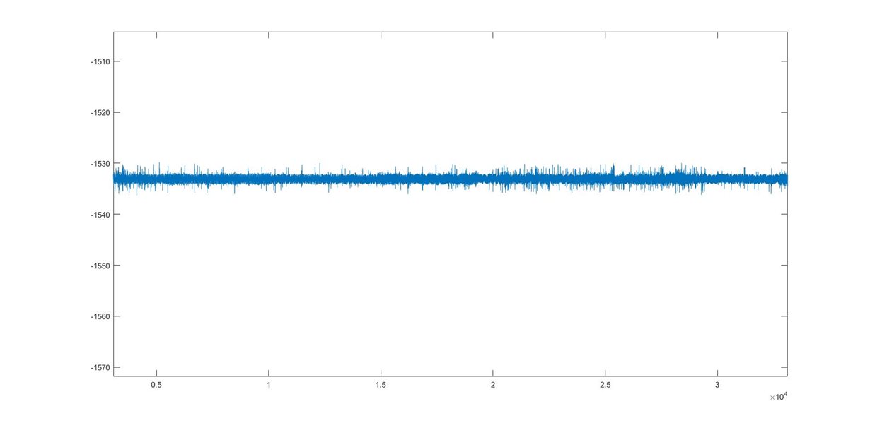
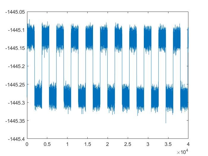
I have been using an ADS1298R development board without the MMB0 DSP processor, Talking directly to the chip via SPI. I have gotten successful results with ECG waveforms simulated using a fluke prosim8. I wanted to test wheater I can read the respiration data from the simulator (configured to output respiration waveforms) through the inbuilt dedicated hardware of the ADS1298R. I was successful in obtaining the test waveform generated by the MSP430 on board. I have attached an image of the waveform below. I then configured it to measure the waveform from the fluke however, all I observed is noise (image below). Here are my register configurations. Have I done something wrong? or is there a different config?
Register configs :
CONFIG4: Configuration Register 4
|
Bit |
Field |
Description |
|
7:5 |
RESP_FREQ[2:0] |
001 = 32 kHz modulation clock |
|
4 |
RESERVED |
Always write 0h |
|
3 |
SINGLE_SHOT |
0 = Continuous conversion mode |
|
2 |
WCT_TO_RLD |
0 = WCT to RLD connection off |
|
1 |
PD_LOFF_COMP |
0 = Lead-off comparators disabled |
|
0 |
RESERVED |
Always write 0h |
write_register(CONFIG4, 0x20u);
CH1SET: Individual Channel Settings
|
Bit |
Field |
Description |
|
7 |
PDn |
0 = Normal operation |
|
6:4 |
GAINn[2:0] |
011 = PGA 3 |
|
3 |
RESERVED |
Always write 0h |
|
2:0 |
MUXn[2:0] |
000 = Normal electrode input |
write_register(CH1SET, 0x30u);
write_register(CH2SET, 0x30u);
RESP: Respiration Control Register
|
Bit |
Field |
Description |
|
7 |
RESP_DEMOD_EN1 |
1 = RESP demodulation circuitry turned on |
|
6 |
RESP_MOD_EN1 |
1 = RESP modulation circuitry turned on |
|
5 |
RESERVED |
Always write 1h |
|
4:2 |
RESP_PH[2:0] |
100 = 112.5° phase |
|
1:0 |
RESP_CTRL[1:0] |
10 = Internal respiration with internal signals |
write_register(RESP, 0xF2u);
The above plot is with the test signal generated by the onboard msp450. below is the plot by the signal generated by the prosim 8 by FLUKE. Note that JP34,35 were switched to electrode inputs.


