This thread has been locked.

If you have a related question, please click the "Ask a related question" button in the top right corner. The newly created question will be automatically linked to this question.

ADS131E08: Data converters forum

Part Number: ADS131E08

Hi community, 

i am using a RPi3 to get the data from the ADS131E08 EVM, i have found that after a while i get corrupted data. 

-using 64 kHz sampling  

- SPI clock 25 MHz 

- the problem interval is random and also when unplugging an input 

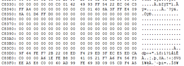
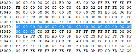
While reading the data from the A2D I get an error as shown in the following pictures 

after the all 00 lines the data are corrupted. 

Thanks. 

  • Kotsilitis,


    It's not clear to me what the problems is based on this set of readings. However, one common problem with corrupted data comes from reading data without using the /DRDY as an interrupt to start the read. This is when the device is in read data continuous mode, which I believe is the default mode.

    Each /DRDY indicates that a conversion has been completed by the ADCs. If you start a read of the device, you want to make sure that the data is completely read out before the next conversion completes. If the read is started and a new conversion is completed, then the data shows up at the DOUT, replacing the data from the previous conversion. From the master's point of view, the data is corrupted.

    To verify this you can use a logic analyzer to look at the SPI communications and see if the /DRDY comes in the middle of a read. I would definitely look at this any time there are problems with corrupted data.

    If this is the problem, and you want to avoid this, you can use /DRDY to trigger an interrupt to read the data. Or you could send the SDATAC command to stop the read data continuous mode and use RDATA commands to read the data.


    Joseph Wu

  • Hi Joseph, 

    In my design I use the DRDY signal in order to get the data from the SPI. The timing seems alright in the analyzer, the problem appears in random intervals or when an input is unplugged from the ADC. 

    another issue that I have is that when using the reference design indicated in page 58 of http://www.ti.com/lit/ds/symlink/ads131e08.pdf   and I am not able to get the readings for the negative AC readings. i have used the filter and all the components for the voltage divider and i connect the ground of the ADS but the negative lobes never appear do you have any idea on that ? 

    Finally, i will try to solve the problem by identifying the 00 lines and reset the ADC in order to start the sampling process from the begging but i wanted to be able to collect the data seamlessly. the RDATA command is not applicable in our case. 

    Thanks,

    Sarantis  

  • Kotsilitis,


    Do you have a schematic that you can share?

    First, for your communication problem, if the problem appears when unplugging an input from the ADC, then maybe the problem has an external component. Perhaps the supply spikes low when a sensor is unplugged. This could cause the device to power down and reset. Do you normally program any of the registers for operation? Can you check the register values to see if they get reset to default after another event like this? You shouldn't need to reset the device and you should be able to get continuous operation. There just may be a problem with the power source.

    For the second problem, when you say that you can't see the negative lobes, are they present on the input when you measure them with an oscilloscope? One thing that I would check would be the supplies. For the design on page 58, the supplies are set to ±2.5V. If you have a unipolar supply (like a single +5V supply), you may be exceeding the input voltage of the ADC by pulling the input below ground.


    Joseph Wu

  • Hi Joseph, 

    the past days i have been validating my design, looks like the EVM board does not have all the components as seen from the BOM table. 

    My circuit in order to sample the AC voltage is the above,  the problem is that when I do not put a ground to the circuit before J7 the waveform has too much noise, when i connect the ground my oscilloscope presents a perfect sinusoidal waveform and I get only the Positive lobes. The ground i use is the one that is available on TP12

    i set my registers as follows: 

    - reg 0x05 -> 0x10 or 0x20 

    -reg  0x06 -> 0x10 

    -reg 0x07-0c -> 80 power down 

    FalutN and FaultP status bits are ok no fault detected.  

    When i connect a voltage transducer instead of the live power line i am able to sample the both positive and negative lobes without any problem 

    the only difference between the two waves is the amplitude the first one is peak to peak 500mV while the second one is peak to peak 1.5 V.

  • Sarantis,


    If the EVM board is missing components, can you let me know what is missing? I'm not sure of the comparison to the board build used in the schematic from the EVM User's Guide to what is used now. I'd need to check with the EVM group to find out about the current build.

    In your last post, there was supposed to be a picture showing the AC Voltage. Can you post that picture again? For the E2E editor, you can't cut and paste pictures into the post. You need to use the Insert/Edit Media icon that looks like a picture frame.

    When you measure the live power line how is the ground connected between the source and the EVM? The input voltage must have a common ground and the input voltage must be in the input range to properly make the measurement.

    To be sure of your connection, can you show a schematic of what you have connected to the EVM? I'm most concerned about the ground connection with the source, to make sure the input is within the ADC range. Also, can you post a picture of the ADC output read? I'd like to see both the output plot of the ADC reading, and the output raw data from the ADC (a collection of the raw hex data would be ok). I'd want to see the result for both the voltage transducer and the power line.


    Joseph Wu

  • Sarantis,

    I haven't heard from you for a while so I thought I'd check in on you. As I mentioned in my last post, I was looking for the image that failed to come up in your last post. I was also asking about what devices in the EVM that were missing and the measurement connections that you were using for the EVM.

    I'll close this post for now. If you are still having problems, post back, and we can continue to work on this again.

    Joseph Wu