This thread has been locked.

If you have a related question, please click the "Ask a related question" button in the top right corner. The newly created question will be automatically linked to this question.

ADS1120: Reading the internal temperature sensor and interpreting the results.

Part Number: ADS1120
Other Parts Discussed in Thread: ADS1220,

I have inherited a project using the TM4C129ENCPDTI3R to read K-type thermocouples from the ADS1220.  I have some example code and will be getting the electrical schematics next week. 

I'm able to read and write to ADS1220 and am curious about the values I am recieving.  When I read the internal temperature sensor, I get a value of 0x11652e, that is then bit shifted by 10 values and that number is multiplied by 0.03125 from page 31 of SBAS535C document. I get a value of ~35 degrees C.

I then attach a k-type thermocouple calibrator to the input and check to see when the ADS1220 is reading around 0, which is when the calibrator outputs 24.6 degrees C. 

Is my math correct for the Internal temperature sensor?

  • Hi Bryan,

    Just so we are clear, are we talking about the ADS1120 or the ADS1220?  Your discussion says ASD1220, but the topic heading is ADS1120.  For now I will assume that you are talking about the ADS1220 as the value you mentioned is 24-bit as opposed to 16-bit.

    Your internal temperature calculation appears to be correct based on the data you have given.  However, it is not clear if you have done an offset calibration for the ADS1220 or how you are specifically using the calibrator.  Can you tell me which calibrator you are using and how it is connected to the ADS1220 as well as the register settings being used?  I think you are basing your measurement assuming that the cold-junction temperature will compensate to 0V, but this may not be the case if there are issues with device offset or input measurement that is outside the measurement range.

    I again assume you are attempting to determine the ambient temperature.  The ADS1220 will come close to the ambient, but it is actually measuring the internal temperature of the silicon die.  As the device is soldered to a PCB (normal operation) the die temperature will also be influenced by board temperature.  This can actually be warmer than the ambient air temperature.

    For the differences you are seeing, this could be due to a number of possible issues.  I mentioned the calibration and board temperature, but noise could also influence what you are seeing.  So it would be helpful for me to see a schematic, board layout and register configuration settings for the ADS1220.    I would also like to see a series of collected data for each measurement case of a minimum of 128 contiguous conversion results.

    Best regards,

    Bob B

  • Thank you Bob for the quick response.

    We are using the ADS1220IPWR, sorry for the confusion.

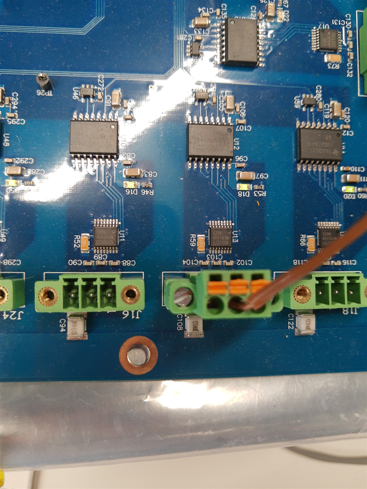
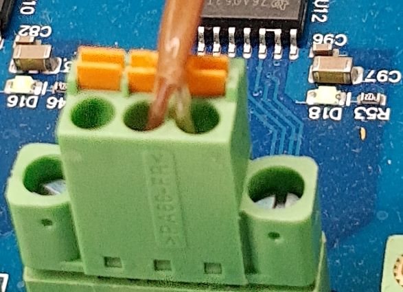
    We are using a Fluke 714 thermocouple calibrator attached to thermocouple wire to our connector on the board.  I have included an image of the distance between the connector and ADS1220.

    The setup command for the ADS1220 are _ADS1220_config[4] = { 0x0A, 0x00, 0x02, 0x00 };.

    I am trying to figure out why the difference between the CJC and the zero threshold of the thermocouple are 10 degrees different.  I know there will be a difference due to noise, design, etc.  I just wasn't expecting it to be that different, but that could have been my expectations.

    The expected heater temperature is around 160 C so we will be tuning the device for the final application around that, but I would still like to read the full range of the K-type thermocouple for testing the design.

    For the offset calibration, I would set the first register to 0xE0 read the value and store that, then use that value when calculating the final temperature?

    How often does the calibration need to happen?  Do you recommend do that on only startup or after XX many hours of continuous operation?

  • What were the registration settings for the 128 different values you want me to take? 

    I can set the 714 to any value you'd want to see.

  • Hi Bryan,

    I was just looking over the information you just sent and I'm still evaluating.  The offset calibration is close to what you described using for register 0.  Instead use 0xEA which keeps the same gain setting as you were using.  The code returned would be subtracted from subsequent  conversions.  You should do this at power-up and depending on the temperature environment of the ADS1220, you might want to do it periodically.  There is really no good answer as to how often it should be done.  When making the offset calibration you may want to take 3-5 samples and average to reduce any noise.

    As to your latest post, I would prefer that you turn the ADS1220 to continuous mode and take 128 conversion samples in a row without skipping any samples.  First use the internal temperature sensor and collect that data, then use the calibrator and take that conversion data.  All I need is one measurement cycle from the calibrator.  Just tell me what voltage out setting you are using.  Also let me know if the data you are giving me is corrected for offset or not.  If not corrected, then let me know the offset code value you determined.

    The layout looks to be good.  The ADS1220 internal temperature sensor should be quite accurate to the cold-junction temperature.  The picture you sent only shows 1 wire at the connection block.  I guess I'm still not quite sure how you are inputting the voltage from the calibrator to the ADS1220.

    Schematically I see you have pull-ups and pull-downs on the input.  However the value is 100k, which might cause some issue with self-heating of the TC.  Also, you have 10nF caps for both the differential and common-mode caps at the input.  The differential cap should be 10x greater in value than the common-mode caps.  The reason is to limit any drift due to mismatch of filter values causing an error in measurement.

    I also see you have an inductance between the DVDD and AVDD sides of the ADS1220.  We have seen that in some cases added inductance can cause issues even when using a ferrite bead choking required current at times the analog portion of the device is powering up circuits.  The ADS1220 current is not static but is dynamic.  I would suggest replacing the inductance with a small value of resistance if you require some supply filtering.

    Best regards,

    Bob B

  • Please find attached an excel sheet of the values.

    I have also attached some quick code I wrote to complete the task.  Was that done properly?

    ADS1220 Fluke714 150.xlsx

    read SSI1 data.c
            volatile int j;
            volatile int32_t data;
            volatile int32_t data1;
            volatile float fint_temp;
            volatile float internal_mv;
            volatile float data_mv;
            volatile float combined_mv;
            volatile float data_c;
            int32_t temp_array[200];
            int32_t internal_array[200];
    
                GPIOPinWrite(GPIO_PORTP_BASE, 0xFF, 0xFF);        //TC 0-5
                GPIOPinWrite(GPIO_PORTQ_BASE, 0x07, 0xFF);        //TC 6-8
    
                //Set chipselect low
                GPIOPinWrite(GPIO_PORTP_BASE, GPIO_PIN_1, 0x00);
    
                //read the cjc
                SSIDataPut(SSI1_BASE, 0x44); // Commands can be decoded to read the value of temperature sensor
                SSIDataPut(SSI1_BASE, 0x06); // internal sensor continous mode.
    
                while (SSIBusy(SSI1_BASE))
                {
                } // Wait until SSI1 is done transferring all the data in the transmit FIFO.
    
                SSIDataGet(SSI1_BASE, &g_garbage_can); // To flash out all garbage data from FIFO
                SSIDataGet(SSI1_BASE, &g_garbage_can); // To flash out all garbage data from FIFO
    
                //Start/Sync - write 0x08
                SSIDataPut(SSI1_BASE, 0x08);
                SSIDataGet(SSI1_BASE, &g_garbage_can);  //clearing Recieve FIFO
    
                SysCtlDelay(ADS1220_DELAY); // Delay a bit (~52ms) for conversion to be completed
    
                SSIDataPut(SSI1_BASE, 0x10); //RDATA command
                SSIDataGet(SSI1_BASE, &g_garbage_can);  //clearing Recieve FIFO
                for( j = 0; j<200; j++)
                            {
    
                                SSIDataPut(SSI1_BASE, 0x00);
                                SSIDataPut(SSI1_BASE, 0x00);
                                SSIDataPut(SSI1_BASE, 0x00);
    
                                //Collect Data
                                SSIDataGet(SSI1_BASE, &g_garbage_can);
                                msb = g_garbage_can;
    
                                SSIDataGet(SSI1_BASE, &g_garbage_can);
                                mid = g_garbage_can;
    
                                SSIDataGet(SSI1_BASE, &g_garbage_can);
                                lsb = g_garbage_can;
    
                                data = byte_combo_3x8to1x24(msb, mid, lsb);
    
                                internal_array[j]=data;
                                SysCtlDelay(ADS1220_DELAY);
                            }
    
                SSIDataPut(SSI1_BASE, 0x44); // Commands can be decoded to read the value of temperature sensor
    
                SSIDataPut(SSI1_BASE, 0x04); // external TC
    
                while (SSIBusy(SSI1_BASE))
                {
                } // Wait until SSI1 is done transferring all the data in the transmit FIFO.
    
                SSIDataGet(SSI1_BASE, &g_garbage_can); // To flash out all garbage data from FIFO
                SSIDataGet(SSI1_BASE, &g_garbage_can); // To flash out all garbage data from FIFO
    
                //Start/Sync - write 0x08
                SSIDataPut(SSI1_BASE, 0x08);
                SSIDataGet(SSI1_BASE, &g_garbage_can);  //clearing Recieve FIFO
                SysCtlDelay(ADS1220_DELAY); // Delay a bit (~52ms) for conversion to be completed
                //Read Command
                SSIDataPut(SSI1_BASE, 0x10); //RDATA command
                SSIDataGet(SSI1_BASE, &g_garbage_can);  //clearing Recieve FIFO
    
                for( j = 0; j<200; j++)
                {
    
                    SSIDataPut(SSI1_BASE, 0x00);
                    SSIDataPut(SSI1_BASE, 0x00);
                    SSIDataPut(SSI1_BASE, 0x00);
    
                    //Collect Data
                    SSIDataGet(SSI1_BASE, &g_garbage_can);
                    msb = g_garbage_can;
    
                    SSIDataGet(SSI1_BASE, &g_garbage_can);
                    mid = g_garbage_can;
    
                    SSIDataGet(SSI1_BASE, &g_garbage_can);
                    lsb = g_garbage_can;
    
                    data = byte_combo_3x8to1x24(msb, mid, lsb);
                    temp_array[j]=data;
                    SysCtlDelay(ADS1220_DELAY);
                }
    
                GPIOPinWrite(GPIO_PORTP_BASE, GPIO_PIN_0, 0xFF);

  • Hi Bryan,

    Thanks for the additional information.  I will send an additional response as soon as I can following a good review of the information.

    Best regards,

    Bob B

  • Hi Bryan,

    I looked at the spreadsheet data.  For the internal temperature sensor data I took the decimal value received from the temp sensor and divided by 1024 (same as right shift by 10).  I then rounded the value to an integer and multiplied by the temperature coefficient of 0.03125 deg C.  I also noted that the temp sensor codes started at about 945 and increased slightly over time to stabilize at about 948-949 codes.  945 is about 29.53125 deg C, and 948 is about 29.625 deg C.  So there is about a 1/10 of a deg C from die heating.  The cold junction compensation would be an added 1.1842 to 1.188mV.

    I also converted the values at both 150 deg C and 500 deg C to voltage values.  In either case when I add the measured voltage with the CJ voltage I get within about 200uV of the expected value.  There is some error with respect to this as the CJ temperature should actually be a part of the normal measurement loop, but based on the consistency of the measurements being so close to 200uV in every case, I believe the CJ temperature was relatively stable.  So in the end the data is pretty much what I would expect.

    I would suggest that you now make the CJ measurement, convert the temperature to a voltage for the TC type you are using and add to the ADC measured voltage then convert back to temperature.  You should get very close to the setting you are using on the calibrator based on these latest measurement results.  It is unclear as to why you were seeing a large difference in your previous measurements.

    Best regards,

    Bob B

  • Thanks Bob for your assistance.  I rewrote CJ measurement and comparing the previous software, it was not handling the milivolts properly between the CJ measurement and the ADC measured voltage.  Now that has been corrected for values of 50-1360 degree C from the meter the software is reading 55-1365, with an approximate offset of +5 degree c at all values.