This thread has been locked.

If you have a related question, please click the "Ask a related question" button in the top right corner. The newly created question will be automatically linked to this question.

AFE5851: Cannot set FINE_GAIN in Static PGA mode

Part Number: AFE5851

Hi, 

I have run into a problem, that I hope you can help me with.

We use several AFE5851 in static PGA mode. While setting COARSE_GAIN register seems to work fine, FINE_GAIN register
does not seem to have any impact on the signal level. Does it require any other register access perhaps that I missed?

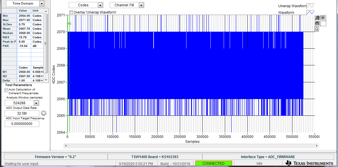
I attached the gain profile when setting COARSE_GAIN only, but it is basically identical with the one when I also increment
FINE_GAIN.

Thank you.
Best regards, 
Peter

  • Hi,

    Thanks for using AFE5851.

    we will reply your question very soon.

    Thank you!

    Best regards,

    Chen

  • Hi,

    Thanks for using AFE5851 device.

    Please try and make sure the following settings:

    1) make sure only use and set => "LSB First"

    2) set address=0x99 data=0x8

    3) set address=0x9A data=0x5 (assume coarse gain=0dB)

    4) then you can set as you want address=0x99 data=(from 0x8 to 0xF)

    then you can see the Gain changed similar to Figure 3 on Datasheet Page 9.

    (note: very tiny change when using FINE_GAIN).

    Please try it.

    Thank you!

    Best regrds,

    Chen

  • Hi Chen,

    Thank you for the prompt answer.
    1) LSB first
    I guess it is supposed to be applied to data decoding. Yes, we use LSB first mode. The data makes sense, so this is not a problem.

    I am sure it was successful to set the registers at 0x99 and 0x9a in the correct order. Let me show some curves of the envelope of our signal with different gain settings.
    1) REG[0x9a]=0x1a, REG[0x99] =0x08, total 21 dB

    2) REG[0x9a]=0x1a, REG[0x99] =0x0F, total 21.875 dB

    3) REG[0x9a]=0x1b, REG[0x99] =0x08, total 22 dB

    I know the setting FINE gain should not impact the data much, but the data with 21.875 dB applied gain should be closer to the one with 22 dB, but it actually looks more like the one with 21 dB. This is why I believe, FINE gain setting does not go through.
    Since FINE gain shares register with static PGA mode bit, I believe I set the registers correctly. It was also confirmed by register readback.
    What else may we miss to set here?
    Thank you.
    Best regards,
    Peter

  • Hi Chen, 

    May I ask if you have any update? Thank you. 

    Best regards, 
    Peter

  • Hi Peter,

    Thank you so much for giving us more detail information.

    We assume you can set register COARSE_GAIN by using the register Address=0x9A  data=0x5 (0dB)

    at this moment, also please set address=0x97  data=0x80

    and set register FINE_GAIN (with Fixed-gain mode) by using the register Address=0x99

    and adjusting data=0x8 (0dB) to 0xF (0.875dB)

    Please try them then you can see them step-by-step.

    Hope this is working fine for you!

    Thank you very much!

    Have a nice day!

    Best regards,

    Chen

  • Hi Chen, 

    Seems like register at 0x97 comes up with 0x8c after power up, so interpolation bit is enabled. I have also tested it with writing 0x80, still getting the same results.

    Have you tried to reproduce my problem on hardware?

    Thank you, 

    Peter

  • Hi Peter,

    sorry, we don't know how you got the register 0x97 0x8C from?

    After at first, you set 0x9A for the Coarse_Gain.

    if when you enter the register 0x97 0x80

    after that then you test the output signal by setting the register from 0x99 0x08 to 0x99 0x0F.

    If you still don't see any Fine_Gain changing,

    then could you please try the following?

    -----------------------------

    Then you enter the register 0x97 0xB6

    and then you test from 0x99 0x08 to 0x99 0x0F.

    Then it should work for you.

    -------------------------

    Could you please let us know if either way works for you or not?

    Thank you very much!

    Best regards,

    Chen

  • Hi Peter,

    How do you test AFE5851EVM on your side?

    Are you using AFE5851EVM with THS1400 Board

    with using AFE5851 GUI on your PC?

    Or you are using your test station?

    Thank you!

    Best regards,

    Chen

  • Hi Chen, 

    Thank you for the reply. 

    No, I do not have AFE5851EVM, I conduct tests on our prototypes. 

    Regarding to register at 0x97... All the 16 ADC on our board came up with default value of 0x8c without any exception.

    I experienced a couple of strange issue with that register though:
    1) Whatever I write into that register, bit 7 will be negated. The rest of the bits are okay.
    So writing 0x80 and reading back 0x00. Writing 0x05, reading back 0x85.

    2) After writing that register, I am not able to disable static gain mode by resetting bit 3 of 0x99. Only issuing software reset (REG[0] <= 1) made static gain enable/disable working. Adjusting COARSE_GAIN still had impact on the data.

    3) Then I managed to make FINE_GAIN working to some extent. I made sure that register at 0x97 has value of 0 (writing 0x80, explained above). I have captured some data (envelope of a test signal).

    COARSE_GAIN=0x14, FINE_GAIN=0x0

    COARSE_GAIN=0x14, FINE_GAIN=0x7

    COARSE_GAIN=0x15, FINE_GAIN=0x0

    It is clearly visible, that FINE_GAIN started to work, but seems like it adds less gain then 0.125 dB/LSB. The signal on the second picture (15.875 dB) is way lower than on the third one (16 dB), however the applied gain is almost identical.

    In order to emphasize this issue, I made my FPGA increment COARSE_GAIN and FINE_GAIN register periodically.

    Coarse gain increments at sample 120 and 480, while between those only FINE_GAIN increments from 0 to 7. 

    On the picture above the effect of FINE_GAIN is clear, but that instant jumps in the signal suggest, the slope of FINE_GAIN is not 0.125 dB.

    For reference I attach the same data acquisition without any FINE_GAIN adjustment:

    Would you please help me understand the symptoms I described above?

    Thank you. 

    Best regards, 

    Peter

  • Hi Peter,

    How are you?

    sorry, first of all,

    could you please try the following settings?

    (to make sure Static PGA='1')

    for your setting: COARSE_GAIN=0x14, FINE_GAIN=0x0 

    => please make sure to be: COARSE_GAIN=0x14, FINE_GAIN=0x08

    for your setting: COARSE_GAIN=0x14, FINE_GAIN=0x7

    => please make sure to be: COARSE_GAIN=0x14, FINE_GAIN=0x0F

    for your setting: COARSE_GAIN=0x15, FINE_GAIN=0x0

    => please make sure to be: COARSE_GAIN=0x15, FINE_GAIN=0x08

    After these changes, please try run again.

    Hopefully this should be working correctly this time.

    Thank you!

    Best regards,

    Chen

  • Hi Chen, 

    I am sorry, but not sure if I understood what exactly I should test. Your suggested steps were the ones I reported in my last post. 

    Best regards, 

    Peter

  • Hi Peter,

    Thanks for making sure.

    Yes, we also try as your same condition

    1) Coarse_gain=0x14, Fine_gain=0x0

    mean = 2067.76 code

    2) Coarse_gain=0x14, Fine_gain=0x7

    mean = 2069.49 code

    3) Coarse_gain=0x15, Fine_gain=0x0

    mean = 2068.23 code

    We believe you are using DC coupling mode,

    However, please look at the AFE5851 datasheet page 9

    for example, please look at Figure 1 and Figure 2 both with signal running at 2MHz.

    these specs are Speced  using AC coupling mode only.

    So please try running your input signal with such as sinewave signal.

    Thank you!

    Best regards,

    Chen

  • Hi Chen, 

    Thank you. 
    We are using AC-coupling.

    While I am trying to reproduce the same here again, may I ask what the value of register 0x97 was during your tests?
    Do you have any explanation on the misbehavior of 0x97 register I described above?

    Peter

  • Hi Peter,

    Here are some examples how we test the AC couple signal

    (in this case, input signal = 2MHz sine wave, clock freq=32.5MHz)

    The important settings are shown (one example of :Coarse_gain=0x14, and Fine_gain=0x0)

    1) Testing at Coarse_gain=0x14, and Fine_gain=0x0.

    And you can see the captured signal is = -9.741dBFS.

    2) Testing at Coarse_gain=0x14, and Fine_gain=0x7.

    And you can see the captured signal is = -8.918dBFS.

    3)  Testing at Coarse_gain=0x15, and Fine_gain=0x0.

    And you can see the captured signal is = -8.738dBFS.

    So here are more captured and calculated from the raw data:

    Then you can see the total Gain (including Coarse Gain and Fine Gain)

    The gain shows the same performance as datasheet on page 9.

    Thank you !

    Best regards,

    Chen

  • Hi Chen,

    Thank you. 

    I would like to ask again, what the register value of 0x97 was during your tests? Do you have any explanation on the misbehavior of that register I described above?

    Best regards, 
    Peter

  • Hi Peter,

    How are you?

    Yes, when you select register 0x97 for Fine Gain (for fixed gain mode)

    then please use the register 0x97 0x86

    This should work for you.

    Since this device has been released long time ago, this had been working this way,

    I really don't know why need to include

    0x97 register for setting Fine Gain at fixed gain mode.

    Very sorry about that.

    Also when you are setting Gain,

    please must set TGC_Reg_EN=ON

    Thank you!

    Best regards,

    Chen

  • Hi Peter,

    How are you?

    Hope you can set up register as same as our setup of AFE5851.

    Thank you!

    Best regards,

    Chen

  • Hi Chen, 

    I have managed to set up that register (0x97) the way you described, but does not have any impact on the gain.
    Found, that when I set bit 7 of 0x97 FINE_GAIN starts to be visible on the data, but it does not seem to 
    have the range of 0 - 0.875 dB.

    Orange curve shows a channel without using incrementing FINE_GAIN, while blue is with FINE_GAIN applied. If FINE_GAIN had the full range, blue curve 
    would not be this staircase like.
    Meanwhile my colleague is trying to reproduce what you saw on EVM, but he is struggling to set the kit up.


    Best regards, 

    Peter

  • Hi,

    Since looks like you are input very low freq signal (looking like DC signal) into AFE5851

    device, therefore please add the following functions (register settings) as:

    (to separate your DC signal out of AC signal from your output data)

    by setting:

    address=0x15   data=0x05

    address=0x21   data=0x05

    then you can only see the AC increment only.

    Thank you and best regards,

    Chen

  • Hi Chen, 

    I am afraid, this did not help.

    Blue is with 0x00 in register 0x15 and 0x21, while in case of orange curve I have set those registers to 0x5. Please note, that ADCs use different starting coarse gain to be able separating them visually.

    Best regards, 

    Peter

  • Hi Peter,

    Just reminding:

    when these two registers 0x15 and 0x21 are used,

    you need to make sure: 

    please make sure to set this register bit: TGC_REGISTER_WREN = "0"

    Please refer to DataSheet Page 18:

    =============

    ADDRESS FUNCTION DESCRIPTION

    0[2]       TGC_REGISTER_WREN         0: Access to general-purpose registers.           1: Access to TGC registers

    =============

    Thank you!

    Best regards,

    Chen

  • Hi Chen, 

    I am reading/writing with otherwise proven methods, that ensures the correct setting of REG[0] to access both general register table and TGC registers.

    Best regards, 

    Peter

  • Hi Chen,
    we have now made more measurements with a sine wave into one of our ADC channels. We collect raw data and frame clock by an FPGA directly from the ADC LVDS and format it in a Python script. We measure the peak of this single sine. We write the registers as follows:
    1) Write 0x0080 to register 0x97
    2) Write 0x0008 + fine gain to register 0x99
    3) write course gain to register 0x9A
    We repeat step 2 and 3 for each new gain setting.
    The ADC comes up in AC-coupling (register 7[1])  mode as default. We increase the fine gain by one step and measure the amplitude. Then we set the mode to DC-coupling and repeat the measurement. The numbers are listed below.
    Gain    AC-coupl DC-coupl

    0.000                   100.97

    0.125   103.60     101.07

    0.250   103.67     101.19

    0.375   103.73     101.30

    0.500   103.79     101.41

    0.625   103.85     101.52

    0.750   103.92     101.65

    0.875   104.02     101.83

    1.000   104.59     102.00

    2.000   105.61     103.02

    3.000   106.62     104.03

    The numbers suggest that the course gain works fine in both AC-coupling and DC-coupling mode. The fine gain is correct in DC-coupled mode, but is halved in AC-coupled mode. Our question is why?
    In your evaluation kit you seem to use differential input channels, while we use single-ended. We feed 16 different signals into the ADC relative to ground, each through a 100nF AC-coupling capacitor. Which mode is correct for us: AC-coupled or DC-coupled?
    The attached picture is the input configuration of the eval kit. In our design, IN1 and IN2 are two different channels and we do not have R39 and R40.
    Best regards, 
    Peter
  • Hi,

    First, for your question on the J1 and J2 plots from your copied picture,

    J1, R39, C56 are independent from J2, R40, C51.

    and using R39 is for the single source needs 50ohm termination.

    (same as R40).

    If you signal source is coming from the other source, you may ignore it due to your different input signal.

    Also our AFE5851EVM is following the datasheet page 16 by using AC coupling method to

    therefore we cannot use it to run DC coupling method.

    So if you want to compare AC coupling and DC coupling differences,

    you need to modify the test board and and register settings as well.

    Therefore if your board is designed for using DC coupling method,

    then your test registers must be setup using DC coupling registers.

    Thank you!

    Best regards,

    Chen

  • Hi,

    Also could you please let us know what is your input sine wave frequency is?

    Is your input signal frequency >1MHz ?

    because as you can see, on the datasheet page 15 "INPUT CONFIGURATION" mentioning

    For the typical frequency used in ultrasound (>1MHz)

    Is your input signal frequency >1MHz ?

    Thank you!

  • Hi Chen, 

    we used 500 kHz sine.

    Best regards, 

    Peter

  • Hi Chen,

    unfortunately we cannot find the answer to our question, so we repeat it.
    1) Why is the gain halved when we go from DC-coupled mode to AC-coupled mode?
    2) What is the correct mode to use when our single-ended input is AC-coupled?

    Thank you, 
    Peter

  • Hi,

    To answer your questions as following:

    1) AFE5851 device is designed for the application of ultrasound which signal frequency is speced as >1MHz (this is shown on the datasheet),

    for your application which input signal is 500kHz, then you recommend you must choose DC-Coupled Mode (register address=0x7, data=0x2).

    Because DC-Coupled Mode can be used for lower input frequency signal.

    2) Your single-ended input signal needed to be connected to a serial Capacitor and then

    this serial cap needed to be connected to the device's input pin such as Ch1 Input to IN1 input pin.

    Please refer to the Datasheet Figure 31 for detail.

    Thank you!

    Best regards,

    Chen

  • Hi Chen, 

    Thank you for clarifying it. I believe this resolved our problem, so I am closing this ticket. 

    Best regards, 

    Peter