This thread has been locked.

If you have a related question, please click the "Ask a related question" button in the top right corner. The newly created question will be automatically linked to this question.

ADS5560: debug help

Part Number: ADS5560

Our KMM customers encounter the following questions during the use of ads5560. Please help to answer them

1、 Whether the clock can adopt the differential clock output by FPGA, or still have to use a special clock chip to form a fully differential clock?

2、 The delay of the output clock controlled by the control pin SEN corresponds to which signal is delayed (input clock, or output data?)?

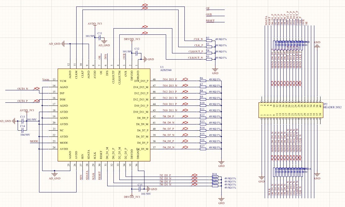
3、 What kind of matching method should be used for impedance matching of data output pins.?The matching method we currently use is to connect a 50Ω resistor between the output pin and GND.The matching circuit of our board is as follows:

 a、a、Waveform before matching:

b、Waveform after matching:


4、Could you provide some data processing routines for ADS5560 when use FPGA?

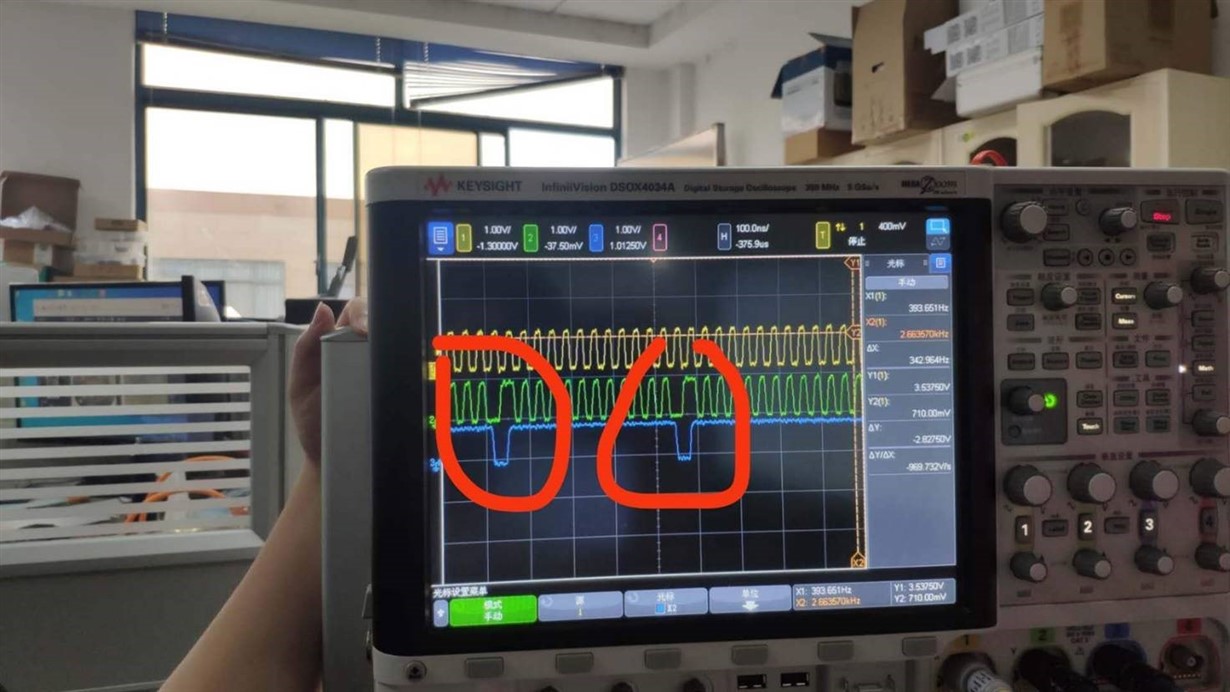
 5、In addition, we compare the difference between our board and ads5560evm: our board uses the differential clock output by FPGA, while ads5560evm uses the clock output by special clock chip. We connect the input to GND and sample data14 and data15 (pin47 and pin48) all the time. Occasionally, we can catch a signal of 1, as shown in the figure below, which leads to the spike of sampling data. I don't know if it's because of the clock signal?


  • Can you please tell the voltage of DFS pin you are using? What's the output mode you are trying to use? I need this info to answer questions 3 and 4

    1. Differential clock from FPGA will work if it meets the differential swing is more than 0.4V p-p. Performance might be limited by clock jitter as the input clock is from FPGA.

    2. Data delay with respect to input clock remains the same. So, output clock is delay controlled by SEN pin is delay with respect to both input clk and output data.

    3. 100 ohm differential termination works for data out pins. So 50 ohms termination to GND on all pins is equivalent to that and will work.

    Regards,

    Vijay

  • DFS voltage is zero, the output data format is two's complement

  • Thanks for your reply, we also encountered a problem.

    The voltage collected by the ADS5560 has random jumps at some voltage points. The problematic voltage points are: 460mV, 650mV, 920mV, 1.00V, 1.11V, 1.2V, 1.36V, 1.52V. Other voltage points can be collected normally.

    The phenomenon appears as follows:

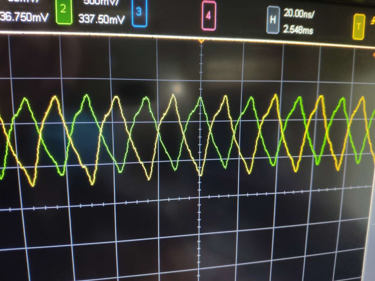
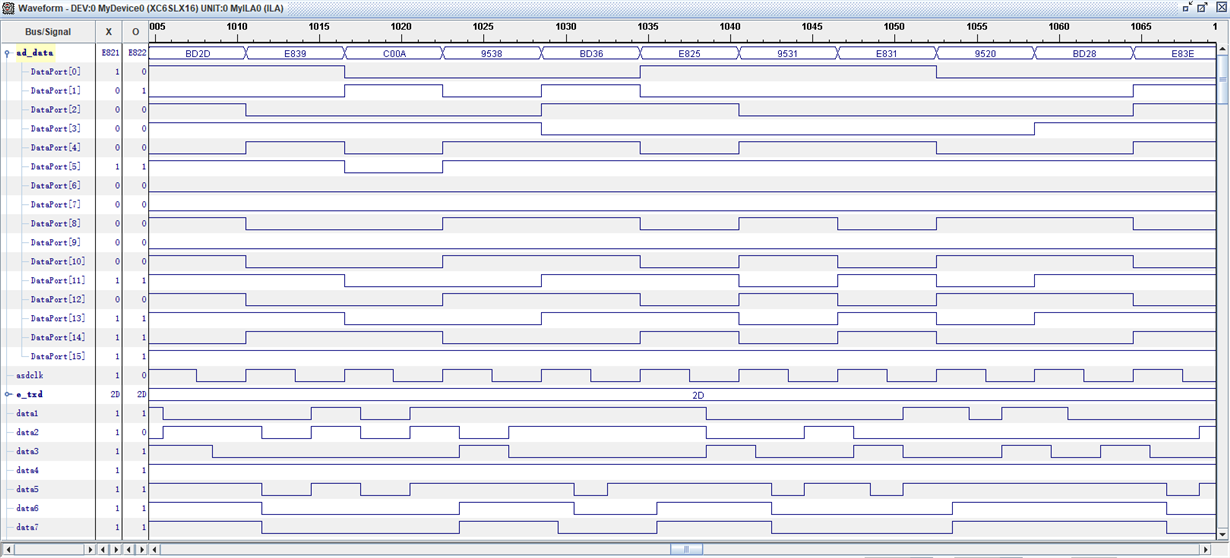
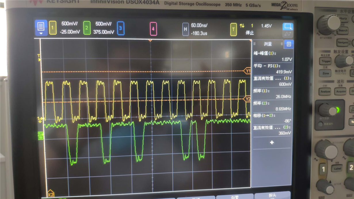
    Collect 1.0V voltage data: (yellow is the clock, green is the data)

    Waveform:

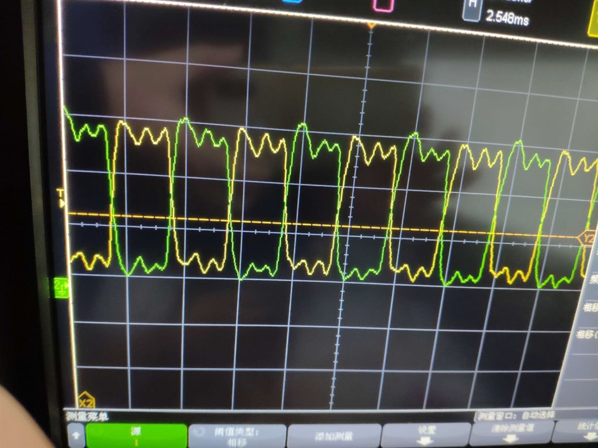
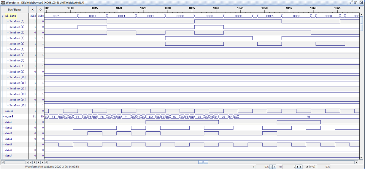
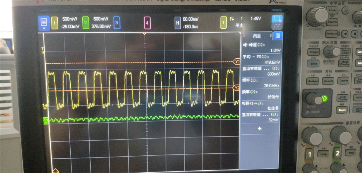
    Collect data of 1.05V voltage:

    Waveform:

    The data at 1.0V and 1.05V are very similar, and the data collected are very different.

    This phenomenon occurs at several other problematic voltage points, and the maximum amplitude of the jump is 1.0V, 1.11V, 1.2V, which is about 2V. The other voltage points have a smaller jitter, about 0.5V.

    Regards,

    jinpin

  • Hi jinpin,

    In the oscilloscope waveform, you said green trace is data. Is it one bit of data? If yes, which bit?

    I suspect that the code jump problem you are seeing might be because of some incorrect bit order interpretation. 

    If you can send slow ramp input and plot the digital output, it would be helpful in debug.

    Regards,

    Vijay

  • Thank you for your reply.

    In the original picture, the yellow line is the clock line, the green line is the data line, and the sampling is the DATA12_13 output pin.

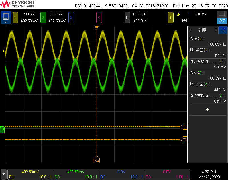
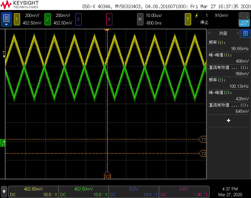
    The following is the waveform after conversion of our sampling input and ADC return value::

    Input differential sine wave (Amplitude: 500mVpp, Frequency: 100KHz, Bias voltage: 250mV)

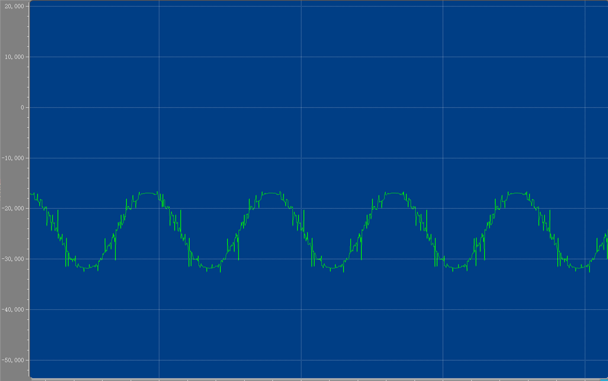
    Sample waveform:


    Input differential triangle wave(Amplitude:500mVpp、Frequency:100KHz、Bias voltage:250mV)

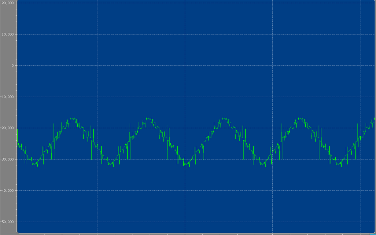
    Sample waveform:

    Both of the sampled waveforms will experience data transitions near the same voltage values. We are also wondering if the data we sampled is misaligned, causing incorrect sampling.

    If so, is there any way to eliminate this effect and improve the sampling accuracy.

    Thanks!

  • Hi jinpin,

    This kind of jump in waveform can occur if some data bits from previous sample are mixed up with data bits from current sample. 

    Are the LVDS output data traces length matched in PCB layout?

    Did you try changing the output clk delay (by varying SEN voltage) to see if it has any impact on data captured?

    Regards,

    Vijay

  • Hi Jinpin,

    Can you send the full analog input and clock input portion of schematic for me to review?

    I especially want to see how is VCM set for the analog input pins. 

    Regards,

    Vijay