This thread has been locked.

If you have a related question, please click the "Ask a related question" button in the top right corner. The newly created question will be automatically linked to this question.

ADS1294R: Issue acquire 3 Lead ECG signal

Part Number: ADS1294R
Other Parts Discussed in Thread: ADS1298

Hi!

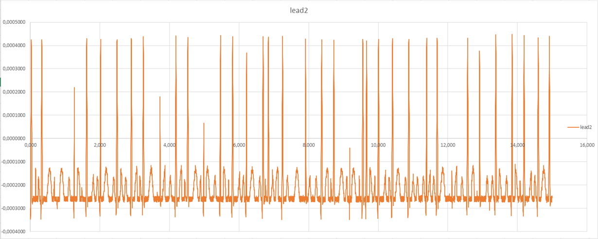
My company is developing a product, with the main purpose of acquire a 3 lead ECG signal from a patient t-shirt. For that, I'm using a ADS1294R. So, my main problem here, is: when i connect my product to a ECG simulator ( Model: AMPS-1 | S/N: PS08060041 ) I can actually see the ECG graph with low noise like you see in the image bellow:

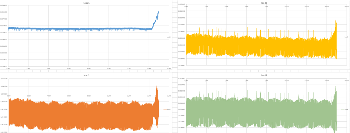
But, when I connect it to my shirt/eletrodes, I cannot see anything good. The next image show the Real ECG measurement:


I'v tested different electrodes in different locations, but nothing seems to work.

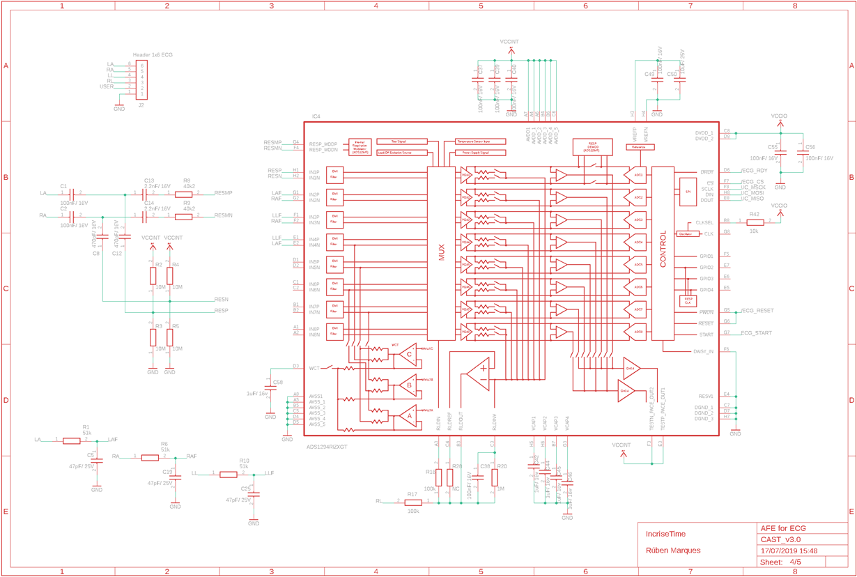
I've review all the software and hardware and nothing seem to be discordant with the datasheet information. However, its my first time, working with this kind of technology, so I may be missing something. I would like you to review my hardware and software configurations and, possibly, help solve my problem.

I will post all the information i can give you in the next topics:

Hardware Configuration:


  • Vref: 2.4V Internally 
  • AVDD: 3.3V 

Software Configuration:

  • LP Mode in 500 sps;
  • Read data in continuous mode;
  • PGA gain = 4;
  • CONFIG1 = 0x05;
  • CONFIG2 = 0x30;
  • CONFIG3 = 0xCC
  • CH1SET, CH2SET, CH3SET, CH4SET = 0x40;
  • RLD_SENSP = 0x0F;
  • RLD_SENSN = 0x0F;
  • RESP = 0xF2;
  • CONFIG4 = 0x20;


Thanks in advance.

Best regards,

André Vaz

  • Hello Andre,

    Thank you for your post.

    If the difference in signal quality is noticed between the patient simulator and a real patient, my assumption would be that the large contact impedance of the dry electrodes is the main issue. Dry cloth electrodes will have much larger contact impedance. This can result in attenuation of your ECG signal. In addition, differences in contact impedance will create a more noticeable common-mode to differential noise conversion, which will mask the signals of interest. 

    We cannot provide much insight into the impedance of the electrodes you're using as we're just don't have the expertise. However, I did review your schematic and one thing I noticed was the very low closed-loop bandwidth of the RLD amplifier. The 1M||100nF sets the bandwidth to 1.59 Hz, meaning none of the 50 Hz / 60 Hz common-mode noise is being rejected by the RLD loop. Please decrease the cap to 1.5nF. This may not completely solve the issue, but it should help reduce the amount of 50Hz/60Hz noise in your measurements.

    Regards,

  • Hello Ryan!

    First of all, thank you for your precious help!

    Indeed, I suspect that the difference in the electrode-skin interface would be the major problem. Because, on the ECG simulator, that's not a issue, right?
    I will try with measure my ECG with some new electrodes I've ordered, and i let you know if the problem is, at least, understated.

    Thanks for that note on the schematic! I thought that the 50Hz noise was filtered on the EMI filter of the ADS1294R. But it the next hardware release i will definitely change that. 

    Best regards,

    André Vaz 

  • Hi Andres,

    The EMI filters have a very high cutoff frequency of about 3 MHz as shown in Figure 24. 

    The RLD loop is intended to sense the common-mode noise on the input electrodes and force a cancellation signal back to the body. This suppresses the amplitude of the common-mode noise, which reduces the amount of noise that converts from common-mode to differential. You want the RLD amplifier to pass 50Hz/60Hz for this reason.

    Best regards,

  • Hi Ryan!

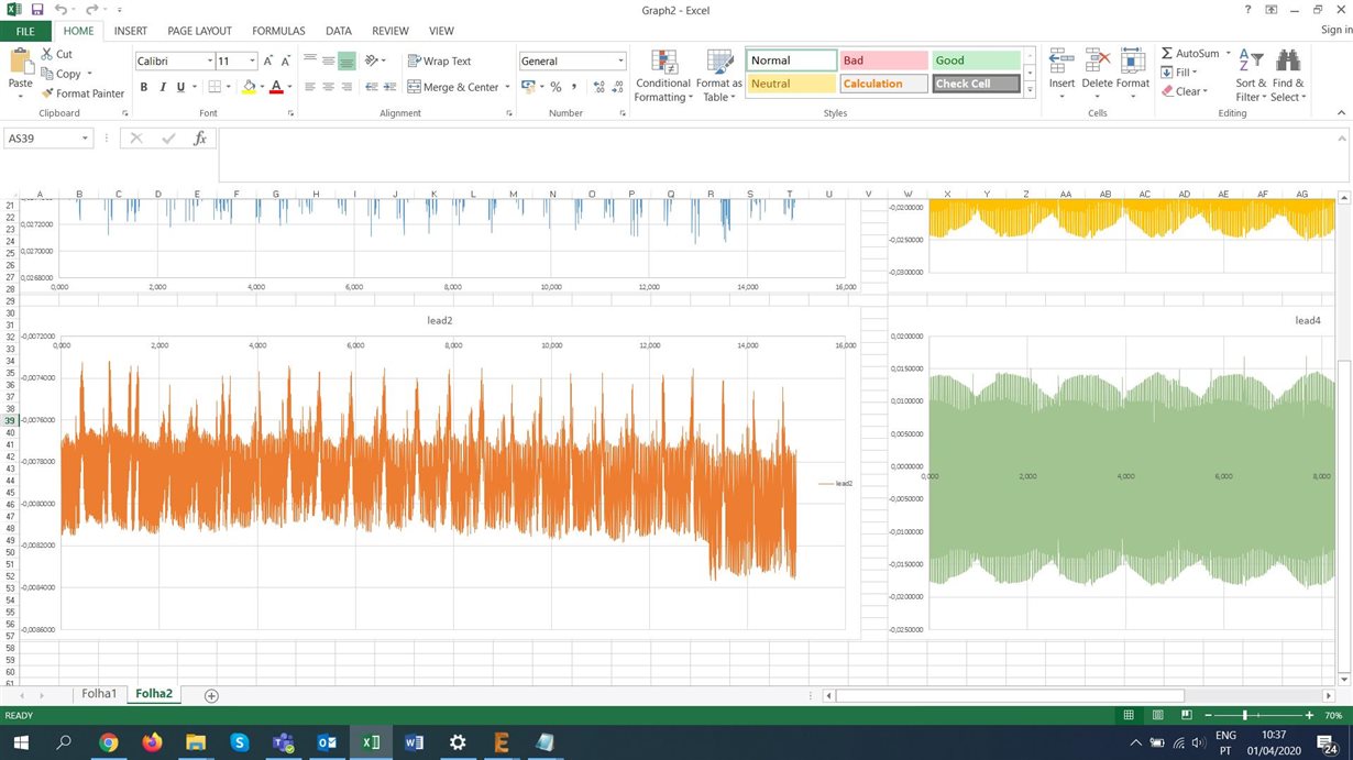
    An update from our talk: I brought some new electrodes and test them again in the better position possible. These ones have some kind of gel for better conductivity. 
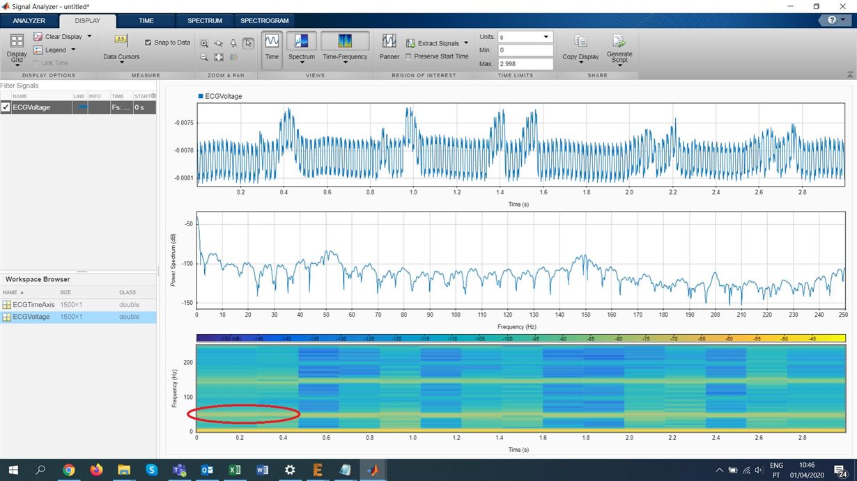
    However, results were almost the same:

    So, I thought on what you wrote about the RLD not not being able to eliminate the 50 Hz noise, but, with the patient simulator, we can, at least see the ECG graph, so I presume that the ADS must be doing some kind of filtering right?

    I'm really running out of options here. I've tried everything. I even built a acquisition signal on a breadboard, tried different kinds of filters, different kind of electrodes and nothing seems to work. Do you have any suggestion on what to do next?

    Best regards,

    André Vaz
     

  • Hi Andres,

    Gel electrodes do lower the contact impedance and should help improve the signal quality. Still, it's possible for a lot of 50-Hz noise to couple onto the body, whereas the patient simulator is shielded and provides a much cleaner signal source to begin with.

    The ADS1294R is not providing much filtering to 50-Hz noise. At 500 SPS, the digital filter has a -3-dB cutoff of 131 Hz.

    In the analog domain, the best you can do is to use shield the cables and circuit board. Also, you need to preserve high CMRR through the analog signal chain by matching input impedances and applying the RLD. A breadboarded circuit is not good for sensitive low-noise measurements as they can be very noisy.

    In the digital domain, ECG applications almost always rely on some digital signal processing to filter out the remaining power line noise.

    Best regards, 

  • Hi Ryan!

    I guess I really need to make changes on my PCB. Since I'm going to do that, i have two questions about the Low Pass Filter on the inputs, and about the RLD.

    Low Pass Filter:

    I'm using first order low pass filter with a cut-off of 66KHz. In many schematics I've seen a lot of different approaches to this filter... Some guy was using a cut-off of 1.5Mhz, and the ADS1298 Evaluation Kit is using a second order filter with a cut-off of 228KHz. So, what do you think that is the best choice to this filter??

    RLD Circuit:

    I have some questions about the RLD circuit.

    1º- Should I filter this signal with a low pass Filter like the others? 

    2º - On your first reply you said i should use a 1M || 1.5nF ( f_coff = 106Hz) on the feedback loop. However, in the Figure 7 of sbaa188.pdf, they use 670k || 1.8nF ( f_coff = 131.97Hz). What is the best choice??

    3º - In my schematic, you can see that I have resistor connecting RLDREF to RLDOUT. However, I'm using the internal Ref ( AVDD + AVSS) /2. Do I need that connection?? 

    4º -  In my schematic, you can see that I have 100k resistor connecting RLDIN to RLDOUT. Do I need that connection, since I'm using a dedicated electrode (RL) to RLD?

    5º - For last, is my R17 well scaled ? What is exactly the function of this resistor?

    Thanks you for all the help Ryan!

    Best regards,

    André Vaz

  • Hi Andre,

    The low-pass filter is needed to attenuate signals near the modulator sampling frequency (1.024 MHz) and prevent them from aliasing into the measurement passband. A cutoff of 1.5 MHz is not going to help. Either of the other options will work. A second-order filter an be set about one decade before the modulator frequency at ~100 kHz and provide about 40 dB of rejection to out-of-band signals. It's more important that the components used have very low tolerances to preserve high CMR.

    Regarding the RLD circuit:

    1. Not necessary to filter the RLD. This signal is common to all electrodes. The R||C feedback already limits the amplifier's bandwidth.
    2. either is ok. The second option will help cancel the second harmonics of 50 Hz / 60 Hz power line noise in addition to the fundamental.
    3. No, the RLDREF pin can be left floating.
    4. No, the RLDIN pin can be left floating.
    5. This is an example of a series protection resistor. Most ECG applications required a limit to the DC current sourced to the body. The exact value and current limit will depend on the class of the medical device and the required standards.

    Best regards,