This thread has been locked.

If you have a related question, please click the "Ask a related question" button in the top right corner. The newly created question will be automatically linked to this question.

CCS/ADS1299EEGFE-PDK: Reading continuou data

Part Number: ADS1299EEGFE-PDK
Other Parts Discussed in Thread: ADS1299

Tool/software: Code Composer Studio

I use MSP432P401R to communicate with ADS1299, I use SPI to read ADS1299 continuous data, MSP432P401R is master, ADS1299 is slave, before that I have successfully used MSP432P401R to write and read the scratchpad, and both were successful, but the reading was continuous There are big problems with the data.
The following is a summary of the problems I have encountered currently:
1. If you want to read the test square wave, and I only need to use one channel, may I ask if all the values of my registers are set correctly, channel 1 is the internal test signal square wave, and the other channels have no signal.
2. When reading continuous data, does the master need to continuously transmit virtual bits 0x00 to slave.
3. When reading continuous data, a stat + 8 channel value will be output between each DRDY, because I only use 1 channel, how do I make the value of channel 1 separate from the other channels.

4. I have tested that the values ​​of channel 1 and other channels are 0x61Input shorted (for offset or noise measurements) x61Input shorted (for offset or noise measurements), but the results show that my SPI seems to be ineffective and cannot receive continuously transmitted data In theory, all values ​​should be 0, but the results have values.

The following is my current code

#include <ti/devices/msp432p4xx/driverlib/driverlib.h>

/* Standard Includes */
#include <stdint.h>
#include <stdbool.h>
#define HZ  3000000UL
/* Statics */
static volatile uint8_t RXData = 0;
static uint8_t TXData = 0;
int i = 0;
int a = 0;
int z = 0;
int j = 0;
//#define A[500];
uint8_t A;
uint32_t B[1000];
//uint8_t A[500];

uint8_t hibyte,midbyte,lowbyte;
uint32_t intQA;

//![Simple SPI Config]
/* SPI Master Configuration Parameter */
const eUSCI_SPI_MasterConfig spiMasterConfig =
{
        EUSCI_B_SPI_CLOCKSOURCE_SMCLK,             // SMCLK Clock Source
        3000000,                                   // SMCLK = DCO = 3MHZ
        500000,                                    // SPICLK = 500khz
        EUSCI_B_SPI_MSB_FIRST,                     // MSB First
        EUSCI_B_SPI_PHASE_DATA_CAPTURED_ONFIRST_CHANGED_ON_NEXT,    // Phase
        EUSCI_B_SPI_CLOCKPOLARITY_INACTIVITY_LOW, // LOW polarity
        EUSCI_B_SPI_3PIN                           // 3Wire SPI Mode
};
//![Simple SPI Config]

int main(void)
{
    /* Halting WDT  */
    WDT_A_holdTimer();

    //![Simple SPI Example]
    /* Selecting P1.5 P1.6 and P1.7 in SPI mode */
    GPIO_setAsPeripheralModuleFunctionInputPin(GPIO_PORT_P1,
            GPIO_PIN5 | GPIO_PIN6 | GPIO_PIN7, GPIO_PRIMARY_MODULE_FUNCTION);

    /* Configuring SPI in 3wire master mode */
    SPI_initMaster(EUSCI_B0_BASE, &spiMasterConfig);

    /* Enable SPI module */
    SPI_enableModule(EUSCI_B0_BASE);

    /* Enabling interrupts */
    //SPI_enableInterrupt(EUSCI_B0_BASE, EUSCI_B_SPI_RECEIVE_INTERRUPT);
    //Interrupt_enableInterrupt(INT_EUSCIB0);
    //Interrupt_enableSleepOnIsrExit();


    //初始化ADS1299

    P3->DIR |= BIT0;
    P3->OUT ^= BIT0; //CS_Low
    __delay_cycles(HZ);
    P3->DIR |= BIT5;
    P3->OUT =  BIT5;       //CLKSEL High
    __delay_cycles(HZ/1000);

    P5->DIR |= BIT1;
    P5->OUT =  BIT1;       //PWDN High
    __delay_cycles(HZ);


    P2->DIR |= BIT7;
    P2->OUT = BIT7;      //RESET High
    __delay_cycles(HZ);


    P2->DIR |= BIT7;
    P2->OUT ^= BIT7;      //RESET LOW
    __delay_cycles(HZ);

    P2->DIR |= BIT7;
    P2->OUT = BIT7;      //RESET High
    __delay_cycles(HZ);
    ///////////////////////////////////////////////////

    while (!(SPI_getInterruptStatus(EUSCI_B0_BASE,EUSCI_B_SPI_TRANSMIT_INTERRUPT)));
    SPI_transmitData(EUSCI_B0_BASE, 0x11);  //SDATAC


    //CONFIG3
    while (!(SPI_getInterruptStatus(EUSCI_B0_BASE,EUSCI_B_SPI_TRANSMIT_INTERRUPT)));
    SPI_transmitData(EUSCI_B0_BASE, 0x43);  //CONFIG3
    while (!(SPI_getInterruptStatus(EUSCI_B0_BASE,EUSCI_B_SPI_TRANSMIT_INTERRUPT)));
    SPI_transmitData(EUSCI_B0_BASE, 0x00);  //CONFIG3
    while (!(SPI_getInterruptStatus(EUSCI_B0_BASE,EUSCI_B_SPI_TRANSMIT_INTERRUPT)));
    SPI_transmitData(EUSCI_B0_BASE, 0xE0);  //CONFIG3

    //CONFIG1
    while (!(SPI_getInterruptStatus(EUSCI_B0_BASE,EUSCI_B_SPI_TRANSMIT_INTERRUPT)));
    SPI_transmitData(EUSCI_B0_BASE, 0x41);
    while (!(SPI_getInterruptStatus(EUSCI_B0_BASE,EUSCI_B_SPI_TRANSMIT_INTERRUPT)));
    SPI_transmitData(EUSCI_B0_BASE, 0x00);
    while (!(SPI_getInterruptStatus(EUSCI_B0_BASE,EUSCI_B_SPI_TRANSMIT_INTERRUPT)));
    SPI_transmitData(EUSCI_B0_BASE, 0x96);//採樣率250


    //CONFIG2
    while (!(SPI_getInterruptStatus(EUSCI_B0_BASE,EUSCI_B_SPI_TRANSMIT_INTERRUPT)));
    SPI_transmitData(EUSCI_B0_BASE, 0x42);
    while (!(SPI_getInterruptStatus(EUSCI_B0_BASE,EUSCI_B_SPI_TRANSMIT_INTERRUPT)));
    SPI_transmitData(EUSCI_B0_BASE, 0x00);
    while (!(SPI_getInterruptStatus(EUSCI_B0_BASE,EUSCI_B_SPI_TRANSMIT_INTERRUPT)));
    SPI_transmitData(EUSCI_B0_BASE, 0xD0);

    //Channel1
    while (!(SPI_getInterruptStatus(EUSCI_B0_BASE,EUSCI_B_SPI_TRANSMIT_INTERRUPT)));
    SPI_transmitData(EUSCI_B0_BASE, 0x45);
    while (!(SPI_getInterruptStatus(EUSCI_B0_BASE,EUSCI_B_SPI_TRANSMIT_INTERRUPT)));
    SPI_transmitData(EUSCI_B0_BASE, 0x00);
    while (!(SPI_getInterruptStatus(EUSCI_B0_BASE,EUSCI_B_SPI_TRANSMIT_INTERRUPT)));
    SPI_transmitData(EUSCI_B0_BASE, 0x65);
    //SPI_transmitData(EUSCI_B0_BASE, 0x61);

    //Channel2
    while (!(SPI_getInterruptStatus(EUSCI_B0_BASE,EUSCI_B_SPI_TRANSMIT_INTERRUPT)));
    SPI_transmitData(EUSCI_B0_BASE, 0x46);
    while (!(SPI_getInterruptStatus(EUSCI_B0_BASE,EUSCI_B_SPI_TRANSMIT_INTERRUPT)));
    SPI_transmitData(EUSCI_B0_BASE, 0x00);
    while (!(SPI_getInterruptStatus(EUSCI_B0_BASE,EUSCI_B_SPI_TRANSMIT_INTERRUPT)));
    SPI_transmitData(EUSCI_B0_BASE, 0x61);

    //Channel3
    while (!(SPI_getInterruptStatus(EUSCI_B0_BASE,EUSCI_B_SPI_TRANSMIT_INTERRUPT)));
    SPI_transmitData(EUSCI_B0_BASE, 0x47);
    while (!(SPI_getInterruptStatus(EUSCI_B0_BASE,EUSCI_B_SPI_TRANSMIT_INTERRUPT)));
    SPI_transmitData(EUSCI_B0_BASE, 0x00);
    while (!(SPI_getInterruptStatus(EUSCI_B0_BASE,EUSCI_B_SPI_TRANSMIT_INTERRUPT)));
    SPI_transmitData(EUSCI_B0_BASE, 0x61);

    //Channel4
    while (!(SPI_getInterruptStatus(EUSCI_B0_BASE,EUSCI_B_SPI_TRANSMIT_INTERRUPT)));
    SPI_transmitData(EUSCI_B0_BASE, 0x48);
    while (!(SPI_getInterruptStatus(EUSCI_B0_BASE,EUSCI_B_SPI_TRANSMIT_INTERRUPT)));
    SPI_transmitData(EUSCI_B0_BASE, 0x00);
    while (!(SPI_getInterruptStatus(EUSCI_B0_BASE,EUSCI_B_SPI_TRANSMIT_INTERRUPT)));
    SPI_transmitData(EUSCI_B0_BASE, 0x61);

    //Channel5
    while (!(SPI_getInterruptStatus(EUSCI_B0_BASE,EUSCI_B_SPI_TRANSMIT_INTERRUPT)));
    SPI_transmitData(EUSCI_B0_BASE, 0x49);
    while (!(SPI_getInterruptStatus(EUSCI_B0_BASE,EUSCI_B_SPI_TRANSMIT_INTERRUPT)));
    SPI_transmitData(EUSCI_B0_BASE, 0x00);
    while (!(SPI_getInterruptStatus(EUSCI_B0_BASE,EUSCI_B_SPI_TRANSMIT_INTERRUPT)));
    SPI_transmitData(EUSCI_B0_BASE, 0x61);

    //Channel6
    while (!(SPI_getInterruptStatus(EUSCI_B0_BASE,EUSCI_B_SPI_TRANSMIT_INTERRUPT)));
    SPI_transmitData(EUSCI_B0_BASE, 0x4A);
    while (!(SPI_getInterruptStatus(EUSCI_B0_BASE,EUSCI_B_SPI_TRANSMIT_INTERRUPT)));
    SPI_transmitData(EUSCI_B0_BASE, 0x00);
    while (!(SPI_getInterruptStatus(EUSCI_B0_BASE,EUSCI_B_SPI_TRANSMIT_INTERRUPT)));
    SPI_transmitData(EUSCI_B0_BASE, 0x61);

    //Channel7
    while (!(SPI_getInterruptStatus(EUSCI_B0_BASE,EUSCI_B_SPI_TRANSMIT_INTERRUPT)));
    SPI_transmitData(EUSCI_B0_BASE, 0x4B);
    while (!(SPI_getInterruptStatus(EUSCI_B0_BASE,EUSCI_B_SPI_TRANSMIT_INTERRUPT)));
    SPI_transmitData(EUSCI_B0_BASE, 0x00);
    while (!(SPI_getInterruptStatus(EUSCI_B0_BASE,EUSCI_B_SPI_TRANSMIT_INTERRUPT)));
    SPI_transmitData(EUSCI_B0_BASE, 0x61);

    //Channel8
    while (!(SPI_getInterruptStatus(EUSCI_B0_BASE,EUSCI_B_SPI_TRANSMIT_INTERRUPT)));
    SPI_transmitData(EUSCI_B0_BASE, 0x4C);
    while (!(SPI_getInterruptStatus(EUSCI_B0_BASE,EUSCI_B_SPI_TRANSMIT_INTERRUPT)));
    SPI_transmitData(EUSCI_B0_BASE, 0x00);
    while (!(SPI_getInterruptStatus(EUSCI_B0_BASE,EUSCI_B_SPI_TRANSMIT_INTERRUPT)));
    SPI_transmitData(EUSCI_B0_BASE, 0x61);


    P2->DIR |= BIT6;
    P2->OUT |= BIT6;    //Set Start High

    while (!(SPI_getInterruptStatus(EUSCI_B0_BASE,EUSCI_B_SPI_TRANSMIT_INTERRUPT)));
    SPI_transmitData(EUSCI_B0_BASE, 0x10);  //RDATAC


    for(i;i<1000;i++)
    {
        int32_t outputcode = adc_read_data();
        B[a] = outputcode;
        a++;
    }
    //PCM_gotoLPM0();
    //__no_operation();
}

uint8_t read_continue_data(){
    SPI_transmitData(EUSCI_B0_BASE, 0x00); //傳送虛擬位元0x00
    A = SPI_receiveData(EUSCI_B0_BASE); //將接收到的資料存進A陣列
    //return read_continue_data;
   // return 0;
}

uint32_t adc_read_data(void)
{
    uint8_t adcCode[3];


    adcCode[0] = read_continue_data();
    adcCode[1] = read_continue_data();
    adcCode[2] = read_continue_data();

    return ((int32_t)(((adcCode[0] & 0x80) ? (0x00) : (0xFF))   ) << 24) |
                                             ((adcCode[0] & 0xFF) << 16) |
                                             ((adcCode[1] & 0xFF) << 8 ) |
                                             ((adcCode[2] & 0xFF) << 0 ) ;
}

  • Hi,

    I'm having trouble reading where your register settings for the ADS1299 are. Can you please post them in a way that is more clear? 

    The data will be output in the form of a 24bit status word along with 24 bits of data for each channel. In order to extract the data only from channel 1, simply read bits 25-48. 

    Even though the other input channels are shorted together, there will still be noise on the outputs. I would expect the output magnitude of these channels to be very small. 

    Please see the BIOFAQ for further information, there is a SPI communication post that should be helpful: https://e2e.ti.com/support/data-converters/f/73/p/772058/2855202

  • I did not put the code of the read register in it, the code of the read register is as follows, ZZ is the value of ADS1299 (0x3E).

    There will always be 216bit output between each DRDY, and 25-48bit is the value of channel 1, so I only need to read the value of 25-48bit each time I read it. Is my understanding correct?

    After my register has a way to communicate correctly, I do n’t know how to read my data continuously, and how to confirm the data is correct?

    #include <ti/devices/msp432p4xx/driverlib/driverlib.h>
    
    /* Standard Includes */
    #include <stdint.h>
    #include <stdbool.h>
    #define HZ  3000000UL
    /* Statics */
    static volatile uint8_t RXData = 0;
    static uint8_t TXData = 0;
    int i = 0;
    int a = 0;
    int z = 0;
    int j = 0;
    //#define A[500];
    uint8_t A;
    uint8_t ZZ;
    uint32_t B[1000];
    //uint8_t A[500];
    
    uint8_t hibyte,midbyte,lowbyte;
    uint32_t intQA;
    
    //![Simple SPI Config]
    /* SPI Master Configuration Parameter */
    const eUSCI_SPI_MasterConfig spiMasterConfig =
    {
            EUSCI_B_SPI_CLOCKSOURCE_SMCLK,             // SMCLK Clock Source
            3000000,                                   // SMCLK = DCO = 3MHZ
            500000,                                    // SPICLK = 500khz
            EUSCI_B_SPI_MSB_FIRST,                     // MSB First
            EUSCI_B_SPI_PHASE_DATA_CAPTURED_ONFIRST_CHANGED_ON_NEXT,    // Phase
            EUSCI_B_SPI_CLOCKPOLARITY_INACTIVITY_LOW, // LOW polarity
            EUSCI_B_SPI_3PIN                           // 3Wire SPI Mode
    };
    //![Simple SPI Config]
    
    int main(void)
    {
        /* Halting WDT  */
        WDT_A_holdTimer();
    
        //![Simple SPI Example]
        /* Selecting P1.5 P1.6 and P1.7 in SPI mode */
        GPIO_setAsPeripheralModuleFunctionInputPin(GPIO_PORT_P1,
                GPIO_PIN5 | GPIO_PIN6 | GPIO_PIN7, GPIO_PRIMARY_MODULE_FUNCTION);
    
        /* Configuring SPI in 3wire master mode */
        SPI_initMaster(EUSCI_B0_BASE, &spiMasterConfig);
    
        /* Enable SPI module */
        SPI_enableModule(EUSCI_B0_BASE);
    
        /* Enabling interrupts */
        //SPI_enableInterrupt(EUSCI_B0_BASE, EUSCI_B_SPI_RECEIVE_INTERRUPT);
        //Interrupt_enableInterrupt(INT_EUSCIB0);
        //Interrupt_enableSleepOnIsrExit();
    
    
        //初始化ADS1299
    
        P3->DIR |= BIT0;
        P3->OUT ^= BIT0; //CS_Low
        __delay_cycles(HZ);
        P3->DIR |= BIT5;
        P3->OUT =  BIT5;       //CLKSEL High
        __delay_cycles(HZ/1000);
    
        P5->DIR |= BIT1;
        P5->OUT =  BIT1;       //PWDN High
        __delay_cycles(HZ);
    
    
        P2->DIR |= BIT7;
        P2->OUT = BIT7;      //RESET High
        __delay_cycles(HZ);
    
    
        P2->DIR |= BIT7;
        P2->OUT ^= BIT7;      //RESET LOW
        __delay_cycles(HZ);
    
        P2->DIR |= BIT7;
        P2->OUT = BIT7;      //RESET High
        __delay_cycles(HZ);
        ///////////////////////////////////////////////////
    
        while (!(SPI_getInterruptStatus(EUSCI_B0_BASE,EUSCI_B_SPI_TRANSMIT_INTERRUPT)));
        SPI_transmitData(EUSCI_B0_BASE, 0x11);  //SDATAC
    
    
        //CONFIG3
        while (!(SPI_getInterruptStatus(EUSCI_B0_BASE,EUSCI_B_SPI_TRANSMIT_INTERRUPT)));
        SPI_transmitData(EUSCI_B0_BASE, 0x43);  //CONFIG3
        while (!(SPI_getInterruptStatus(EUSCI_B0_BASE,EUSCI_B_SPI_TRANSMIT_INTERRUPT)));
        SPI_transmitData(EUSCI_B0_BASE, 0x00);  //CONFIG3
        while (!(SPI_getInterruptStatus(EUSCI_B0_BASE,EUSCI_B_SPI_TRANSMIT_INTERRUPT)));
        SPI_transmitData(EUSCI_B0_BASE, 0xE0);  //CONFIG3
    
        //CONFIG1
        while (!(SPI_getInterruptStatus(EUSCI_B0_BASE,EUSCI_B_SPI_TRANSMIT_INTERRUPT)));
        SPI_transmitData(EUSCI_B0_BASE, 0x41);
        while (!(SPI_getInterruptStatus(EUSCI_B0_BASE,EUSCI_B_SPI_TRANSMIT_INTERRUPT)));
        SPI_transmitData(EUSCI_B0_BASE, 0x00);
        while (!(SPI_getInterruptStatus(EUSCI_B0_BASE,EUSCI_B_SPI_TRANSMIT_INTERRUPT)));
        SPI_transmitData(EUSCI_B0_BASE, 0x96);//採樣率250
    
    
        //CONFIG2
        while (!(SPI_getInterruptStatus(EUSCI_B0_BASE,EUSCI_B_SPI_TRANSMIT_INTERRUPT)));
        SPI_transmitData(EUSCI_B0_BASE, 0x42);
        while (!(SPI_getInterruptStatus(EUSCI_B0_BASE,EUSCI_B_SPI_TRANSMIT_INTERRUPT)));
        SPI_transmitData(EUSCI_B0_BASE, 0x00);
        while (!(SPI_getInterruptStatus(EUSCI_B0_BASE,EUSCI_B_SPI_TRANSMIT_INTERRUPT)));
        SPI_transmitData(EUSCI_B0_BASE, 0xD0);
    
        //Channel1
        while (!(SPI_getInterruptStatus(EUSCI_B0_BASE,EUSCI_B_SPI_TRANSMIT_INTERRUPT)));
        SPI_transmitData(EUSCI_B0_BASE, 0x45);
        while (!(SPI_getInterruptStatus(EUSCI_B0_BASE,EUSCI_B_SPI_TRANSMIT_INTERRUPT)));
        SPI_transmitData(EUSCI_B0_BASE, 0x00);
        while (!(SPI_getInterruptStatus(EUSCI_B0_BASE,EUSCI_B_SPI_TRANSMIT_INTERRUPT)));
        SPI_transmitData(EUSCI_B0_BASE, 0x65);
        //SPI_transmitData(EUSCI_B0_BASE, 0x61);
    
        //Channel2
        while (!(SPI_getInterruptStatus(EUSCI_B0_BASE,EUSCI_B_SPI_TRANSMIT_INTERRUPT)));
        SPI_transmitData(EUSCI_B0_BASE, 0x46);
        while (!(SPI_getInterruptStatus(EUSCI_B0_BASE,EUSCI_B_SPI_TRANSMIT_INTERRUPT)));
        SPI_transmitData(EUSCI_B0_BASE, 0x00);
        while (!(SPI_getInterruptStatus(EUSCI_B0_BASE,EUSCI_B_SPI_TRANSMIT_INTERRUPT)));
        SPI_transmitData(EUSCI_B0_BASE, 0x61);
    
        //Channel3
        while (!(SPI_getInterruptStatus(EUSCI_B0_BASE,EUSCI_B_SPI_TRANSMIT_INTERRUPT)));
        SPI_transmitData(EUSCI_B0_BASE, 0x47);
        while (!(SPI_getInterruptStatus(EUSCI_B0_BASE,EUSCI_B_SPI_TRANSMIT_INTERRUPT)));
        SPI_transmitData(EUSCI_B0_BASE, 0x00);
        while (!(SPI_getInterruptStatus(EUSCI_B0_BASE,EUSCI_B_SPI_TRANSMIT_INTERRUPT)));
        SPI_transmitData(EUSCI_B0_BASE, 0x61);
    
        //Channel4
        while (!(SPI_getInterruptStatus(EUSCI_B0_BASE,EUSCI_B_SPI_TRANSMIT_INTERRUPT)));
        SPI_transmitData(EUSCI_B0_BASE, 0x48);
        while (!(SPI_getInterruptStatus(EUSCI_B0_BASE,EUSCI_B_SPI_TRANSMIT_INTERRUPT)));
        SPI_transmitData(EUSCI_B0_BASE, 0x00);
        while (!(SPI_getInterruptStatus(EUSCI_B0_BASE,EUSCI_B_SPI_TRANSMIT_INTERRUPT)));
        SPI_transmitData(EUSCI_B0_BASE, 0x61);
    
        //Channel5
        while (!(SPI_getInterruptStatus(EUSCI_B0_BASE,EUSCI_B_SPI_TRANSMIT_INTERRUPT)));
        SPI_transmitData(EUSCI_B0_BASE, 0x49);
        while (!(SPI_getInterruptStatus(EUSCI_B0_BASE,EUSCI_B_SPI_TRANSMIT_INTERRUPT)));
        SPI_transmitData(EUSCI_B0_BASE, 0x00);
        while (!(SPI_getInterruptStatus(EUSCI_B0_BASE,EUSCI_B_SPI_TRANSMIT_INTERRUPT)));
        SPI_transmitData(EUSCI_B0_BASE, 0x61);
    
        //Channel6
        while (!(SPI_getInterruptStatus(EUSCI_B0_BASE,EUSCI_B_SPI_TRANSMIT_INTERRUPT)));
        SPI_transmitData(EUSCI_B0_BASE, 0x4A);
        while (!(SPI_getInterruptStatus(EUSCI_B0_BASE,EUSCI_B_SPI_TRANSMIT_INTERRUPT)));
        SPI_transmitData(EUSCI_B0_BASE, 0x00);
        while (!(SPI_getInterruptStatus(EUSCI_B0_BASE,EUSCI_B_SPI_TRANSMIT_INTERRUPT)));
        SPI_transmitData(EUSCI_B0_BASE, 0x61);
    
        //Channel7
        while (!(SPI_getInterruptStatus(EUSCI_B0_BASE,EUSCI_B_SPI_TRANSMIT_INTERRUPT)));
        SPI_transmitData(EUSCI_B0_BASE, 0x4B);
        while (!(SPI_getInterruptStatus(EUSCI_B0_BASE,EUSCI_B_SPI_TRANSMIT_INTERRUPT)));
        SPI_transmitData(EUSCI_B0_BASE, 0x00);
        while (!(SPI_getInterruptStatus(EUSCI_B0_BASE,EUSCI_B_SPI_TRANSMIT_INTERRUPT)));
        SPI_transmitData(EUSCI_B0_BASE, 0x61);
    
        //Channel8
        while (!(SPI_getInterruptStatus(EUSCI_B0_BASE,EUSCI_B_SPI_TRANSMIT_INTERRUPT)));
        SPI_transmitData(EUSCI_B0_BASE, 0x4C);
        while (!(SPI_getInterruptStatus(EUSCI_B0_BASE,EUSCI_B_SPI_TRANSMIT_INTERRUPT)));
        SPI_transmitData(EUSCI_B0_BASE, 0x00);
        while (!(SPI_getInterruptStatus(EUSCI_B0_BASE,EUSCI_B_SPI_TRANSMIT_INTERRUPT)));
        SPI_transmitData(EUSCI_B0_BASE, 0x61);
    
    
        P2->DIR |= BIT6;
        P2->OUT |= BIT6;    //Set Start High
    
        while (!(SPI_getInterruptStatus(EUSCI_B0_BASE,EUSCI_B_SPI_TRANSMIT_INTERRUPT)));
        SPI_transmitData(EUSCI_B0_BASE, 0x10);  //RDATAC
    
        ZZ = spi_read(0x20);// read ads1299ID(0x3E)
    
    
        for(i;i<1000;i++)
        {
            int32_t outputcode = adc_read_data();
            B[a] = outputcode;
            a++;
        }
        //PCM_gotoLPM0();
        //__no_operation();
    }
    
    uint8_t read_continue_data(){
        SPI_transmitData(EUSCI_B0_BASE, 0x00); //傳送虛擬位元0x00
        A = SPI_receiveData(EUSCI_B0_BASE); //將接收到的資料存進A陣列
        //return read_continue_data;
       // return 0;
    }
    
    uint32_t adc_read_data(void)
    {
        uint8_t adcCode[3];
    
    
        adcCode[0] = read_continue_data();
        adcCode[1] = read_continue_data();
        adcCode[2] = read_continue_data();
    
        return ((int32_t)(((adcCode[0] & 0x80) ? (0x00) : (0xFF))   ) << 24) |
                                                 ((adcCode[0] & 0xFF) << 16) |
                                                 ((adcCode[1] & 0xFF) << 8 ) |
                                                 ((adcCode[2] & 0xFF) << 0 ) ;
    }
    
    //read register
    uint8_t spi_read(uint8_t reg) {
    
      // Make sure transmit buffer is clear
      while (!(SPI_getInterruptStatus(EUSCI_B0_BASE,EUSCI_B_SPI_TRANSMIT_INTERRUPT)));
      SPI_transmitData(EUSCI_B0_BASE, reg);                 // Transmit register address
      SPI_transmitData(EUSCI_B0_BASE, 0x00);
      SPI_transmitData(EUSCI_B0_BASE, 0x00);
    // Make sure transmit buffer is clear
    
      while (!(SPI_getInterruptStatus(EUSCI_B0_BASE,EUSCI_B_SPI_RECEIVE_INTERRUPT)));
      RXData = SPI_receiveData(EUSCI_B0_BASE);      // Pick up received byte in SPI receive data register
    
      return RXData;
    }
    //////////////////////////////////////////////

  • Hi,

    That's the correct device ID, so that is good. 

    In order to read continuously, you simply send SCLKS to clock out the data after each DRDY pulse from the ADS1299. In order to confirm that the data is correct, give a known voltage to the ADS1299 input then record what codes are output. Use the BIOFAQ to convert the codes from the ADS1299 back to voltage to confirm that everything is working correctly. 

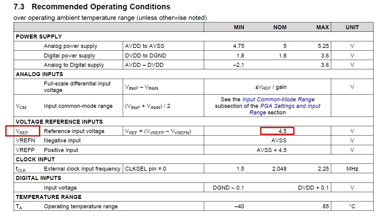
  • I have referred to the method described in this article (e2e.ti.com/.../2856893, I do not understand the value of VREF? 4.5V on the 7th page of the ads1299 datasheet (pictured)? Or is there any way to determine the value of VREF?

  • Hi,

    If you are using the internal reference, it will be 4.5V. You can confirm this by measuring across VREP and VREFN using a multi-meter. If using an external reference, then it will be whatever reference voltage you have set.