This thread has been locked.

If you have a related question, please click the "Ask a related question" button in the top right corner. The newly created question will be automatically linked to this question.

ADS1120: Wiring for 2 RTD (PT100 / PT1000) in 2 wires mode

Part Number: ADS1120
Other Parts Discussed in Thread: ADS114S06

Hi all,

My question is regarding the ADS1120 part and two RTD wiring in two wires mode.

This part have Two Differential or Four Single-Ended Inputs inputs (AIN0 .. AIN3).

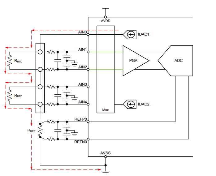
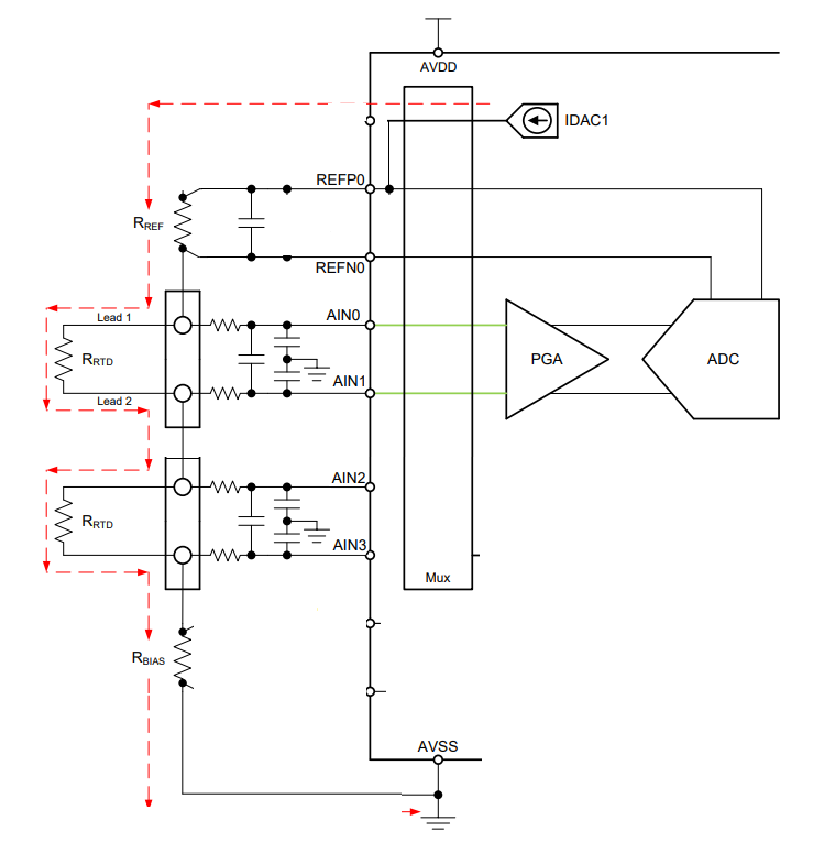
Is it possible to use it as described in "A Basic Guide to RTD Measurement" §2.7 (the following picture). I mean, can I send the current provided by one of the IDAC to AIN0 output and make a differential measurement between AIN0 & AIN1 for the first RTD and a second measurement between AIN2 & AIN3 for the 2nd RTD.

Thank you,

Best Regards,

Paul.

  • Hi Paul,

    In theory you could drive the current out AIN0 and also use the AIN0 input, but there is a potential problem when doing so. If you place a resistor in the input path there will be an associated voltage drop across the resistor creating an error in the measurement.  If you do not use an input resistor you will not have an antialiasing filter or input protection from transients or over-voltage conditions.

    When using the ADS1120 a different approach is possible where you use a high-side reference similar to section 2.2 and figure 8 of SBAA275. I've attached a basic block diagram below:

    Best regards,

    Bob B

  • Hi Bob,

    Thank you for this answer, your proposal is very interesting.

    However we have several other constraints for this application (a professional oven for reheat food for collective catering).
    We design one board for a range of different oven:

    • The 2nd RTD is optional (it is not mounted on some devices)
      If the current must flow through the 1st RTD and the 2nd RTD, I need to replace the not mounted RTD (when not used) by a wire to keep a closed current path.
    • The heat regulation is always  done on 1st RTD, the 2nd RTD is only used for specific cycles.
      If the current path is open (2nd RTD removed by user for example), all the cycles which doesn't need the 2nd RTD are no more possible without a hardware modification.

    So I thought to the block diagram below, is it possible to use the ADS1120 like that?

    • The ADC reference will be the internal reference 2.048Volts. So I suppose that I don't need a resistor between REFP0 & REFN0.
    • The current from IDAC1 flowing from REFP0 is used for the 1st RTD a 1st Rbias close the loop to AVSS.
      Differential measurement is done on AIN0 & AIN1.
      IDAC setting and PGA will help us to maximize the ADC resolution on temperature range.
      I can use the input resistor for antialiasing filter and input protection from transients or over-voltage conditions.
    • The current from IDAC2 flowing from REFN0 is used for the 2nd RTD a 2nd Rbias close the loop to AVSS.
      Differential measurement is done on AIN2 & AIN3.

    Best regards,

    Paul

  • Hi Paul,

    Your design will work, but there will be some error associated with the measurement, primarily due to drift.  The purpose of using the reference resistor is to make the measurement ratiometric.  In this way the code result is a ratio of the RTD to the reference resistor value regardless of the excitation source drift or initial error.  When using the internal reference as the conversion reference source any drift of the internal reference or the IDAC will be reflected in the measurement result.

    I would suggest taking a look at the ADS114S06 which has the capability for two reference inputs.  Another possible option using the ADS1120 is using a mux (or switch) to steer the current from where it flows from the RREF of my original diagram to each of the RTDs individually.

    Best regards,

    Bob B