This thread has been locked.

If you have a related question, please click the "Ask a related question" button in the top right corner. The newly created question will be automatically linked to this question.

ADS1220: About Settling time and Latency

Guru 21045 points
Part Number: ADS1220

Hi Team,


I have two questions.


----------

[Q1]

We use two differential signals (AIN0 & AIN1 pair, AIN2 & AIN3 pair).

Then, we would like to know the following settling time.


My guess Sequence

1.AIN0 & AIN1 pair are ON and AIN2 & AIN3 pair are OFF

2.To change the differential signals

3.AIN0 & AIN1 pair are OFF and AIN2 & AIN3 pair are ON

4.To occur the settling time ??us (we must wait more than ??us)

5.AIN2 & AIN3 pair data are available for AD conversion

----------


[Q2]

We would like to know the latency(Wait time of from Input analog date to Output digital data).

Could you please let us know if you have any information?

----------


Regards,

Hide

  • Hi Hide,

    The answer to the first question is going to be based on mode of operation selected, either single-shot or continuous conversion.  In single-shot mode you would capture the conversion results and change the mux to the next input pair to be converted.  You would then issue the START/SYNC command to start the conversion and time until conversion results are ready is determined by the last SCLK falling edge of the command to the falling edge of the DRDY.  The timing is described in the ADS1220 datasheet in section 8.3.5 and the conversion times are listed as number of tclk periods in the far right column of table 11.

    If operating in continuous mode, the conversion will restart following the register write (WREG) command to change the mux.  The length of time is shown in table 11 in the column for CONTINUOUS CONVERSION MODE.  The time begins with the last falling edge of SCLK of the WREG data to the falling edge of DRDY.

    To maximize throughput when cycling through the mux channels, it is best to run in continuous mode and send the WREG command for changing the mux at the same time the previous conversion result is read.  An example of the process is shown in figure 66 on page 38 of the ADS1220 datasheet.

    The second question is a little more difficult to answer as the method of conversion is done by oversampling the input signal (256kHz in normal mode), placing sampled input data as part of a modulator bit stream and processing through a digital FIR low-pass filter.  So Delta-Sigma converters such as the ADS1220 are typically used in DC or slow moving signal applications.  The latency from the input signal to the output data result is determined by where the signal changes within each data period. A simple way of looking at this would be to take a number of averages of a period where there is a step change. Depending where in time the step occurs will determine the impact on the average.

    For the ADS1220 each conversion result is considered as fully settled and valid data with an output data rate of the results at the selected output data rate.

    Best regards,

    Bob B

  • Hi Bob-san,


    Thank you for the information.


    [Q1]

    I understand that there is no clear the settling time and waiting time is different by mode of operation selected.


    [Q2]

    I understand that there is no clear the latency time and have to measure “A simple way of looking at this would be to take a number of averages of a period where there is a step change”.


    If my understanding is mistaken, please tell me.


    Regards,

    Hide

  • Hi Hide,

    [Q1] Settling time is mostly determined by external analog circuitry.  Each output of the conversion result will be valid and fully settled for the sampling period which is also called single-cycle settling.  So there is no filter latency for the ADS1220 like there could be for some other Delta-Sigma ADCs that use a high order SINC filter.

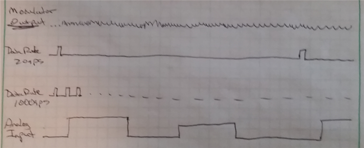
    [Q2] I made a quick drawing.  The drawing is not to scale, but it should show what I'm talking about.

    The top line indicates the input sampling at 256kHz and is 1's density output from the modulator.  The second line is indicating the period of time for 20sps and the third line for 1000sps.  Each pulse indicates when the conversion result is ready to be retrieved.  The bottom line is indicating the actual analog input.  During the 20sps period the input changes many times, but the conversion result is a single code.  At 1000sps the output will more closely follow the input.

    You might find this article helpful:

    http://www.ti.com/lit/an/slyt264/slyt264.pdf

    Best regards,

    Bob B

  • Hi Bob-san,


    Thank you for always kind support and detail information.


    [Q1]

    I understand that Settling time is mostly determined by external analog circuitry.


    [Q2]

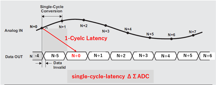
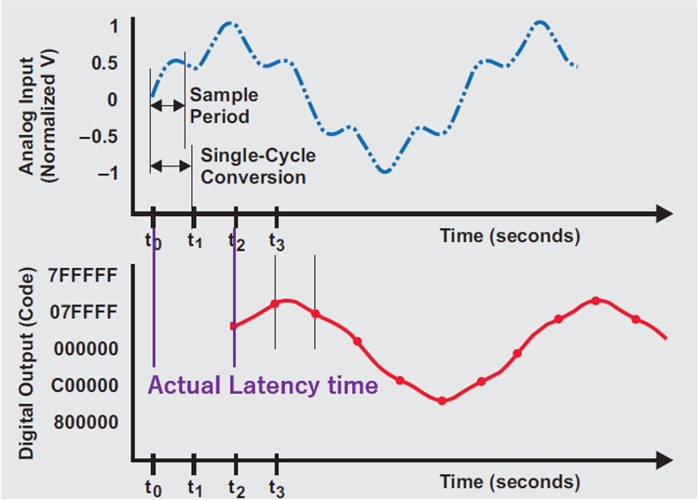
    I understand that " ADC cycle latency of single-cycle" occurs and the latency time depended on the data rates.

    Then, I have to measure an actual latency time, according to your comment.


    [Your comment]

    The latency from the input signal to the output data result is determined by where the signal changes within each data period.

    A simple way of looking at this would be to take a number of averages of a period where there is a step change.

    Depending where in time the step occurs will determine the impact on the average.


    [Image]


    Regards,

    Hide

  • Hi Hide,

    One more comment I wish to make.  Latency for Delta-Sigma ADCs is also dependent on the type of digital filter being used.  Some devices will have a sinc filter.  When a sinc filter is used with a mux, the order of the filter will determine the length of time, or number of data samples, required before the digital filter settles.  For example, when a sinc4 filter is used, it will take 4 cycles to completely settle the data following a mux change and the data are valid on the 5th cycle.

    The ADS1220 uses an FIR digital filter and the data are valid at the end of every conversion cycle.  When muxing channels with the ADS1220, the digital filter is automatically reset when the mux channels are changed.  The next falling edge of DRDY signals that data are available and the data are fully settled and valid.  So in this case all data are valid and follows the selected data output rate.  There is no additional latency when using the ADS1220 due to the digital filter.

    Best regards,

    Bob B